Mitsubishi L200. Manual - part 120
TROUBLESHOOTING
DIESEL FUEL
13A-276
• The engine-ECU checks whether the amount of
current for driving duty is adequate.
TROUBLE JUDGMENT
Check Conditions
• Battery positive voltage is 8 − 16 V
• 2 seconds later after the ignition switch has been
in "ON" position or the engine has started up.
• The supply pump and injector are being normally
controlled.
• The fuel injection rate is 4 mm
3
/st or more.
Judgment Criterion
• When the driving duty ratio of the suction control
valve is higher than the specified value, the driv-
ing current is lower than the specified value.
PROBABLE CAUSES
• Failed suction control valve
• Open/short circuit or harness damage in suction
control valve circuit or loose connector contact
• Failed engine-ECU
DIAGNOSIS PROCEDURE
STEP 1. Connector check: A-47 suction control
valve connector
Q: Is the check result normal?
YES :
Go to Step 2 .
NO :
Repair or replace the connector.
STEP 2. Check suction control valve itself.
• Check suction control valve itself (Refer to
Q: Is the check result normal?
YES :
Go to Step 3 .
NO :
Replace the suction control valve.
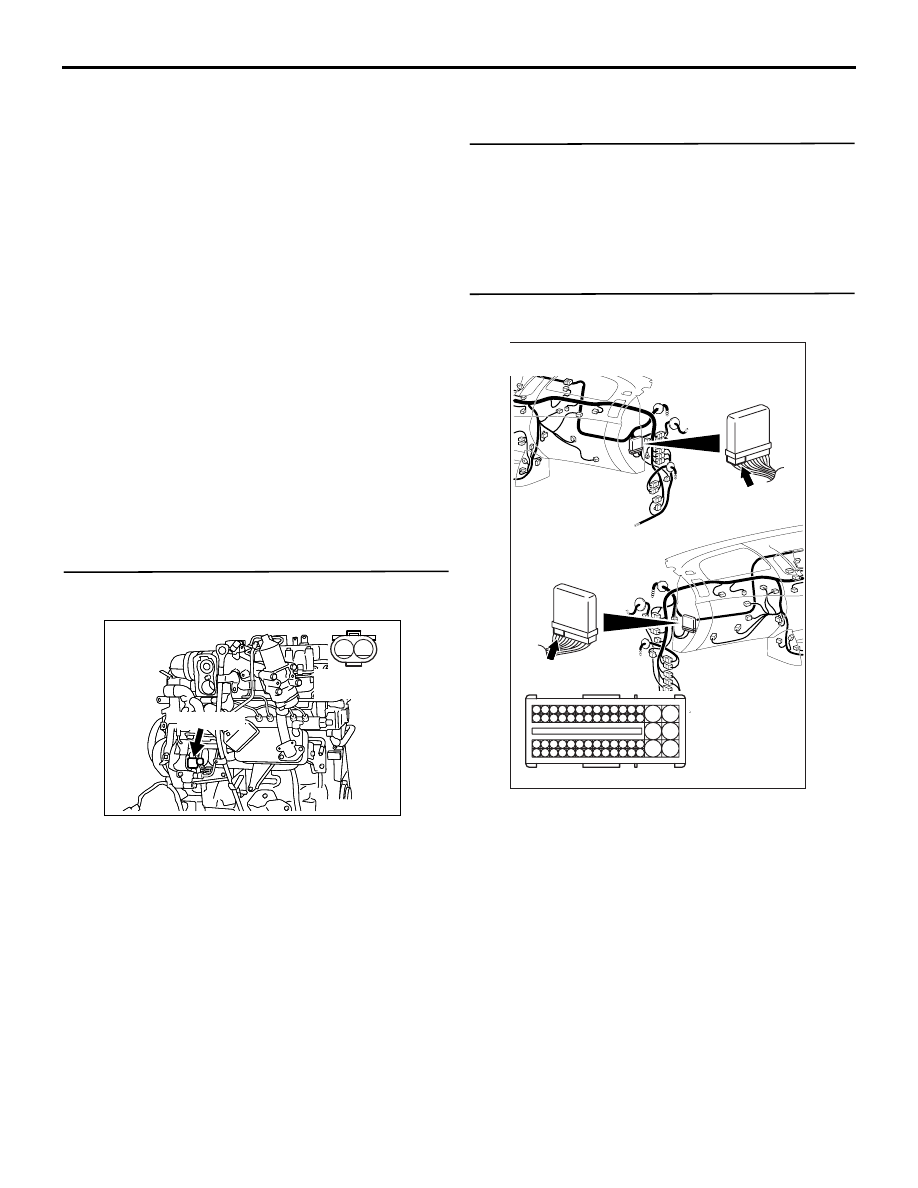
STEP 3. Connector check: C-103 engine-ECU
connector
Q: Is the check result normal?
YES :
Go to Step 4 .
NO :
Repair or replace the connector.
AK503644
2
1
A-47 (GR)
Harness side
connector
AB
Connector: A-47
AKA00090
101
102
103
104
105
106
107
108
109
110
111
112
113
114
115
118
119
120
121
122
123
124
125
126
127
128
129
130
131
132
133
134
135
136
137
138
139
140
141
142
143
146
147
148
149
150
151
152
153
154
155
156
157
158
117
145
116
144
C-103 (B)
C-103 (B)
<R.H. drive vehicles>
Harness side connector
<L.H. drive vehicles>
Connector: C-103
AB