Mitsubishi L200. Manual - part 79


  Index      Mitsubishi     Mitsubishi L200 - service repair manual 2012 year


Search            


Content   ..  77  78  79  80   ..


Mitsubishi L200. Manual - part 79


TROUBLESHOOTING

DIESEL FUEL

13A-112

Code No. P0117: Engine Coolant Temperature Sensor Circuit Low Input

OPERATION

• A power voltage of 5 V is applied to the engine 

coolant temperature sensor output terminal (ter-
minal No. 1) from the engine-ECU (terminal No. 
63).

• The power voltage is earthed to the engine-ECU 

(terminal No. 87) from the engine coolant temper-
ature sensor (terminal No. 2).

FUNCTION

• The engine coolant temperature sensor converts 

the engine coolant temperature into a voltage sig-
nal, and inputs the voltage to the engine-ECU.

• In response to the signal, the engine-ECU con-

trols the fuel infection amount and the fast idle 
speed when the engine is cold state.

• The engine coolant temperature sensor is a kind 

of resistor, which has characteristics to reduce its 
resistance as the engine coolant temperature 
rises. Therefore, the sensor output voltage varies 
with the engine coolant temperature, and 
becomes lower as the engine coolant tempera-
ture rises.

TROUBLE JUDGMENT

Check Conditions

• Battery positive voltage is 8 − 16 V

• 2 seconds later after the ignition switch has been 

in "ON" position or the engine has started up.

Judgment Criterion

• The engine coolant temperature sensor output 

voltage is 0.15 V or less for 0.5 second.

PROBABLE CAUSES

• Failed engine coolant temperature sensor
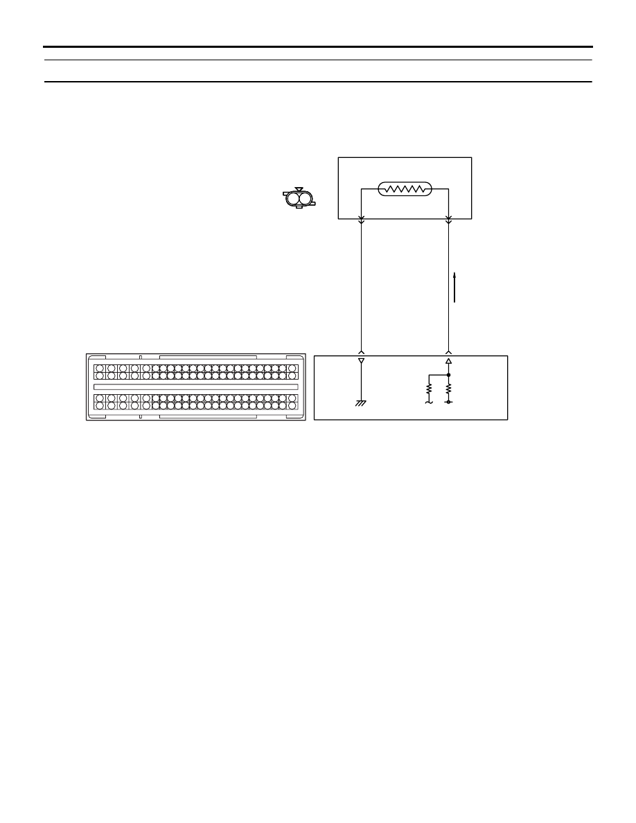
AKA00095

1 2

1 2

1

2

3

4

5 6 7 8 9

10 1112 13 14 15 16 17 18 19 20 21 22 23 24

25 26

27 28 29 30 31 32 33 34 35 36 37 38 39 40 41 42

49 50 51 52 53 54 55 56 57 58 59 60 61 62 63 64 65 66 67 68 69 70 71 72

43 44 45 46 47 48

73 74 75 76 77 78 79 80 81 82 83 84 85 86 87 88 89 90 91 92 93 94 95 96

LG

V

Engine-ECU

Engine coolant
temperature sensor

A-107

(MU802406)

C-105

Engine Coolant Temperature Sensor Circuit

Wire colour code
B: Black  LG: Light green  G: Green  L: Blue  W: White  Y: Yellow  SB: Sky blue  BR: Brown  O: Orange  GR: Grey
R: Red  P: Pink  V: Violet  PU: Purple  SI: Silver

2

87

1

63

AB

TROUBLESHOOTING

DIESEL FUEL

13A-113

• Short circuit or harness damage in engine cool-

ant temperature sensor circuit or loose connector 
contact

• Failed engine-ECU

DIAGNOSIS PROCEDURE

STEP 1. M.U.T.-III data list

• Item 7: Engine coolant temperature sensor

OK:

Engine cold state: At ambient temperature 

(atmospheric temperature) or equivalent.

Engine hot state: At 80 

 120°C

Q: Is the check result normal?

YES : 

Intermittent malfunction (Refer to GROUP 

00 

− How to Use Troubleshooting/

Inspection Service Points 

− How to Cope 

with Intermittent Malfunctions ).

NO : 

Go to Step 2 .

STEP 2. Connector check: A-107 engine coolant 
temperature sensor connector

Q: Is the check result normal?

YES : 

Go to Step 3 .

NO : 

Repair or replace the connector.

STEP 3. Perform resistance measurement at A-
107 engine coolant temperature sensor 
connector.

• Disconnect connector, and measure at sensor 

side.

• Resistance between terminal No. 1 and No. 2.

OK:

Engine coolant temperature at 

20°C: 14  17 

k

Engine coolant temperature at 0

°C: 5.1  6.5 

k

Engine coolant temperature at 20

°C: 2.1  2.7 

k

Engine coolant temperature at 40

°C: 0.9  1.3 

k

Engine coolant temperature at 60

°C: 0.48  

0.68 k

Engine coolant temperature at 80

°C: 0.26  

0.36 k

Q: Is the check result normal?

YES : 

Go to Step 4 .

NO : 

Replace the engine coolant temperature 
sensor.

STEP 4. Perform voltage measurement at A-107 
engine coolant temperature sensor connector.

• Disconnect connector, and measure at harness 

side.

• Ignition switch: ON

• Voltage between terminal No. 1 and earth.

OK: 4.5 

 4.9 V

Q: Is the check result normal?

YES : 

Go to Step 8 .

NO : 

Go to Step 5 .

AK501323

1

2

AB

A-107 (B)

Harness side 
connector

Connector: A-107

AK501323

1

2

AB

A-107 (B)

Harness side 
connector

Connector: A-107

AK501323

1

2

AB

A-107 (B)

Harness side 
connector

Connector: A-107

TROUBLESHOOTING

DIESEL FUEL

13A-114

STEP 5. Connector check: C-105 engine-ECU 
connector

Q: Is the check result normal?

YES : 

Go to Step 6 .

NO : 

Repair or replace the connector.

STEP 6. Check harness between A-107 (terminal 
No. 1) engine coolant temperature sensor 
connector and C-105 (terminal No. 63) engine-
ECU connector.

• Check output line for short circuit.

Q: Is the check result normal?

YES : 

Go to Step 7 .

NO : 

Repair the damaged harness wire.

STEP 7. M.U.T.-III data list

• Item 7: Engine coolant temperature sensor

OK:

Engine cold state: At ambient temperature 

(atmospheric temperature) or equivalent.

Engine hot state: At 80 

 120 °C

Q: Is the check result normal? 

AKA00089

1

2

3

4

5

6

7

8

9

10

11

12

13

14

15

16

17

18

19

20

21

22

23

24

25

26

27

28

29

30

31

32

33

34

35

36

37

38

39

40

41

42

49

50

51

52

53

54

55

56

57

58

59

60

61

62

63

64

65

66

67

68

69

70

71

72

43

44

45

46

47

48

73

74

75

76

77

78

79

80

81

82

83

84

85

86

87

88

89

90

91

92

93

94

95

96

C-105 (B)

C-105 (B)

<R.H. drive vehicles>

Harness side connector

<L.H. drive vehicles>

Connector: C-105

AB

AK501323

1

2

AB

A-107 (B)

Harness side 
connector

Connector: A-107

AKA00089

1

2

3

4

5

6

7

8

9

10

11

12

13

14

15

16

17

18

19

20

21

22

23

24

25

26

27

28

29

30

31

32

33

34

35

36

37

38

39

40

41

42

49

50

51

52

53

54

55

56

57

58

59

60

61

62

63

64

65

66

67

68

69

70

71

72

43

44

45

46

47

48

73

74

75

76

77

78

79

80

81

82

83

84

85

86

87

88

89

90

91

92

93

94

95

96

C-105 (B)

C-105 (B)

<R.H. drive vehicles>

Harness side connector

<L.H. drive vehicles>

Connector: C-105

AB

TROUBLESHOOTING

DIESEL FUEL

13A-115

YES : 

Intermittent malfunction (Refer to GROUP 

00 

− How to Use Troubleshooting/

Inspection Service Points 

− How to Cope 

with Intermittent Malfunctions ).

NO : 

Replace the engine-ECU. When the engine-
ECU is replaced, write the chassis number 
(Refer to GROUP 00 

− Precautions Before 

Service 

− How to Perform Chassis Number 

Writing ). After replacing the engine-ECU, 
register the injector identification code and 
learn fuel injection (Refer to GROUP 00 

− 

Precautions Before Service 

− What The 

Common Rail Engine Learns ). After 
registering the injector identification code, 
the vehicle equipped with the DPF carries 
out the forcible DPF regeneration. (Refer to 
GROUP 17 

− Emission Control − Diesel 

Particulate Filter (DPF) System 

− Forcible 

DPF Regeneration ).

STEP 8. Perform resistance measurement at A-
107 engine coolant temperature sensor 
connector.

• Disconnect connector, and measure at harness 

side.

• Resistance between terminal No. 2 and earth.

OK: Continuity (2 

 or less)

Q: Is the check result normal?

YES : 

Go to Step 11 .

NO : 

Go to Step 9 .

STEP 9. Connector check: C-105 engine-ECU 
connector

Q: Is the check result normal? 

YES : 

Go to Step 10 .

NO : 

Repair or replace the connector.

AK501323

1

2

AB

A-107 (B)

Harness side 
connector

Connector: A-107

AKA00089

1

2

3

4

5

6

7

8

9

10

11

12

13

14

15

16

17

18

19

20

21

22

23

24

25

26

27

28

29

30

31

32

33

34

35

36

37

38

39

40

41

42

49

50

51

52

53

54

55

56

57

58

59

60

61

62

63

64

65

66

67

68

69

70

71

72

43

44

45

46

47

48

73

74

75

76

77

78

79

80

81

82

83

84

85

86

87

88

89

90

91

92

93

94

95

96

C-105 (B)

C-105 (B)

<R.H. drive vehicles>

Harness side connector

<L.H. drive vehicles>

Connector: C-105

AB


Content   ..  77  78  79  80   ..