Mitsubishi L200. Manual - part 13
SUPPLEMENTAL RESTRAINT SYSTEM (SRS)
GENERAL
00-48
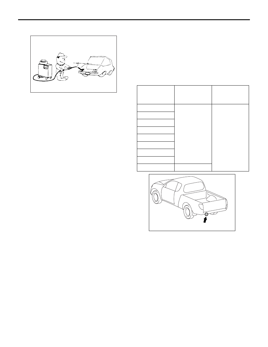
VEHICLE WASHING
M1001012000723
AC300832AC
Approximately
40 cm or more
If high-pressure car-washing equipment or steam
car-washing equipment is used to wash the vehicle,
be sure to note the following information in order to
avoid damage to plastic components, etc.
• Spray nozzle distance: Approx. 40 cm or more
• Spray pressure: 3,900 kPa or less
• Spray temperature: 82°C or less
• Time of concentrated spray to one point: within
30 sec.
PRECAUTIONS FOR INSTALLATION OF
ON-VEHICLE RADIO TRANSMISSION
EQUIPMENT
M1001015500095
The computers (control unit) for various on-vehicle
electronic equipment are provided with sufficient pro-
tective measures against external radio wave inter-
ference. However, because the on-vehicle radio
transmission equipment may affect adversely the
computers (control unit), pay attention to the follow-
ing precautions for installation.
• Install radio transmission equipment and antenna
(including coaxial cables) 200 mm or more away
from the computers (control unit) for on-vehicle
electronic equipment.
• Because radio wave is radiated from the coaxial
cables of the antenna for radio transmission
equipment, do not route the cables in parallel with
the vehicle wiring harness.
• Install only radio transmission equipment with the
frequencies, output, and radio wave types
described in the table.
FREQUENCY, OUTPUT, AND RADIO WAVE
TYPE OF THE RADIO TRANSMISSION
EQUIPMENT
Frequency
(MHz)
Maximum
output power
(W)
Modulation
3.5
50
CW, FM, AM,
SSB
7
14
21
28
50
144
430
1,260
2
•
AC709451AB
Antenna attachment position
Install the antenna for radio transmission equipment
only to the position shown in the figure.
SUPPLEMENTAL RESTRAINT SYSTEM (SRS)
M1001009801120
The driver’s and passenger’s air bag and seat belt
with pre-tensioner is designed to supplement the
driver's and front passenger's seat belts to help
reduce the risk or severity of injury to the driver and
front passenger by activating and deploying both
front air bags in certain frontal collisions. The side-air
bag and the curtain air bag are activated when an
impact exceeds the threshold upon a side collision,
and inflates to protect the heads of the occupants in
the front and rear seats.
The Supplemental Restraint System (SRS) consists
of air bag modules, SRS air bag control unit (SRS-
ECU), front impact sensors, side impact sensor, SRS
warning lamp, clock spring, passenger’s air bag cut
off switch, passenger’s air bag cut off indicator lamp
and seat belt with pre-tensioner. Front air bags are
located in the centre of the steering wheel and above
the glove box. Side-airbags are located inside the
front seatback assemblies. The curtain air bag mod-
ule is installed in the roof side sections (from the