Mitsubishi L200. Manual - part 10


  Index      Mitsubishi     Mitsubishi L200 - service repair manual 2012 year


Search            


Content   ..  8  9  10  11   ..


Mitsubishi L200. Manual - part 10


PRECAUTIONS BEFORE SERVICE

GENERAL

00-36

NOTE: 

.

*

1

: Vehicles with rear step bumper assembly.

PRECAUTIONS BEFORE SERVICE

SERVICING COMMON RAIL ENGINE

M1001016400154

DANGER

The working near to a naked flame or 
sparks must be avoided.

Attention during engine running:

a.

Do not work on the high pressure fuel 
circuit.

b.

Always remain out of the way of possi-
ble fuel jet that may result in serious 
injuries.

c.

Do not place your hand near the high 
pressure fuel circuit.

Attention before service:

a.

After turning the ignition switch to the 
"LOCK" (OFF) position, wait for 30 sec-
onds before starting any repair 
work.This period of time is required so 
that the high pressure fuel circuit pres-
sure can get back to the atmospheric 
pressure.

b.

After turning the ignition switch to the 
"LOCK" (OFF) position, wait 10 min-
utes before disconnecting the fuel 
return pipe from diesel injectors.

VEHICLES WITH SEMI AUTOMATIC AIR 
CONDITIONER STARTING

M1001011300077

CAUTION

Never start the engine with the refrigerant system 
empty as it will damage the A/C compressor.
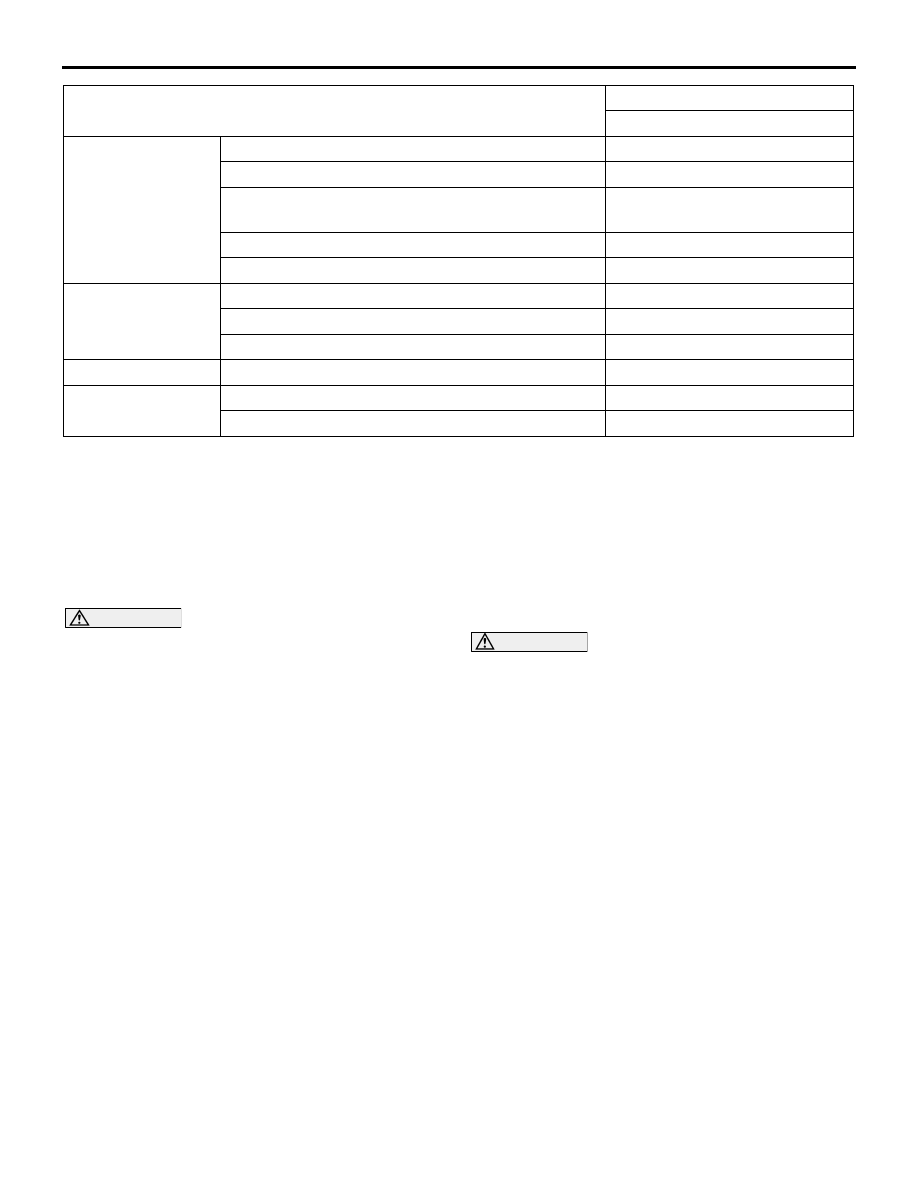
Engine

Model code

4D56

Total displacement mL

2,477

Type

DOHC diesel
Intercooled, Turbocharger

Max. output kW/rpm (EEC net)

94/4,000

Max. torque N

⋅m/rpm (EEC net)

240/1,500 

− 3,500

Transmission

Model code

R5MB1

Type

5M/T

Drive system

Rear wheel drive 2WD

Fuel system

Fuel supply system

Electrical fuel injection 

Turning radius m

Body

6.1

Wheel

5.7

Item

KA4T
NENMZ6BA

PRECAUTIONS BEFORE SERVICE

GENERAL

00-37

SUPPLEMENTAL RESTRAINT SYSTEM 
(SRS) AND SEAT BELT WITH PRE-
TENSIONER

M1001011601695

CAUTION

Items to review when servicing SRS:

1. Be sure to read GROUP 52B 

 Supplemental 

Restraint System (SRS). For safe operation, 
please follow the directions and heed all 
warnings.

2. Wait at least 60 seconds after disconnecting 

the battery cable before doing any further 
work. The SRS system is designed to retain 
enough voltage to deploy the air bag even 
after the battery has been disconnected. Seri-
ous injury may result from unintended air bag 
deployment if work is done on the SRS sys-
tem immediately after the battery cable is dis-
connected.

3. Warning/Caution labels must be heeded when 

servicing or handling SRS components. 
Warning labels can be found in the following 
locations. (Refer to WARNING/CAUTION 
LABELS .)

4. Always use the designated special tools and 

test equipment.

5. Store components removed from the SRS in a 

clean and dry place. The air bag module 
should be stored on a flat surface and placed 
so that the pad surface is facing upward. Do 
not place anything on top of it.

6. Never attempt to disassemble or repair the 

SRS components (SRS-ECU, air bag module 
and clock spring).

7. Whenever you finish servicing the SRS, check 

the SRS warning lamp operation to make sure 
that the system functions properly.

8. Be sure to deploy the air bag before dispos-

ing of the air bag module or disposing of a 
vehicle equipped with an air bag (Refer to 
GROUP 52B 

 Air Bag Module Disposal Pro-

cedures).

Observe the following when carrying out opera-
tions on places where SRS components are 
installed, including operations not directly 
related to the SRS air bag.

1. When removing or installing parts, do not 

allow any impact or shock to the SRS compo-
nents.

2. If heat damage may occur during paint work, 

remove the SRS-ECU, the air bag module, 
clock spring, the front impact sensor, and the 

seat belt pre-tensioner.

• SRS-ECU, air bag modules, clock spring 

and impact sensors: 93

° C or more

• Seat belt with pre-tensioner: 90°C or more

SERVICING ELECTRICAL SYSTEM

M1001011900303

CAUTION

Before connecting or disconnecting the negative 
(

) cable, be sure to turn off the ignition switch 

and the lighting switch (If this is not done, there 
is the possibility of semiconductor parts being 
damaged).

AC300693

Before replacing a component related to the electri-
cal system and before undertaking any repair proce-
dures involving the electrical system, be sure to first 
disconnect the negative (

−) cable from the battery in 

order to avoid damage caused by short-circuiting.

IN ORDER TO PREVENT VEHICLES 
FROM FIRE

M1001011100147

"Improper installation of electrical or fuel related parts 
could cause a fire. In order to retain the high quality 
and safety of the vehicle, it is important that any 
accessories that may be fitted or modifications/
repairs that may be carried out which involve the 
electrical or fuel systems, must be carried out in 
accordance with MMC's information/Instructions".

PRECAUTIONS BEFORE SERVICE

GENERAL

00-38

MULTI USE TESTER (M.U.T.-III) SUB 
ASSEMBLY

M1001012400215

AC305090

MB991910

MB991826

MB991911

MB991825

MB991824

MB991827

AK

Do not use

Vehicle communication interface (V.C.I.)

M.U.T.-III main harness A

M.U.T.-III USB cable

M.U.T.-III main harness B

M.U.T.-III trigger harness

Multi use tester (M.U.T.-III) 
sub assembly

M.U.T.-III measurement adapter

Refer to the "M.U.T.-III OPERATION MANUAL" for 
instructions on handling the M.U.T.-III.

CAUTION

Turn the ignition switch to the "LOCK" (OFF) 
position before connecting or disconnecting the 
M.U.T.-III.

AC509179

AB

Diagnosis

connector

MB991827

MB991824 

MB991910

<LH drive vehicles>

AC501413AC

Diagnosis

connector

MB991827

MB991824 

MB991910

<RH drive vehicles>

Connect the M.U.T.-III to the diagnosis connector as 
shown in the illustration.

HOW TO PERFORM CHASSIS NUMBER 
(CHASSIS NO.) WRITING

M1001015200715

Write the Chassis Number (Chassis No.) of immobi-
liser system as following procedure.

PRECAUTIONS BEFORE SERVICE

GENERAL

00-39

The Chassis Number (Chassis No.) is stored in the 
engine-ECU or ETACS-ECU by the vehicle manufac-
ture. If the Chassis No. to be stored in the engine-
ECU or ETACS-ECU is eliminated fraudulently, the 
engine warning lamp illuminates and Diagnostic 
Trouble Code (diagnosis code) No.P0630 (Chassis 

No. malfunction) is shown. When the engine-ECU or 
ETACS-ECU is replaced, and entry of the Chassis 
No. necessary due to diagnosis code No. P0630 
(Chassis No. malfunction). Enter the Chassis No. in 
accordance with the procedure as follows:

AC510087

System choice

IMMOBILIZER

Special Function

Engine Key Code 
Reg. & Chassis No. 
Writing

Key Code Registration to Engine-ECU

Key Code Registration Completed

Confirmation of Chassis No. writing 
execution

Chassis No. Writing

Chassis No. Writing Completed

Result of Chassis No. Writing

Coding

IMMOBILIZER & Chassis No. 
Writing

Chassis No. Writing 
Completed

Chassis No. Information

Chassis No. Writing

Chassis No. Information

Writing confirmation

Chassis No. Writing

Writing Result Display

AE

SCREEN FLOW OF M.U.T.-III

Engine Key Code Reg. & 
Chassis No. Writing


Content   ..  8  9  10  11   ..