Mitsubishi L200. Manual - part 2
HOW TO USE THIS MANUAL
GENERAL
00-4
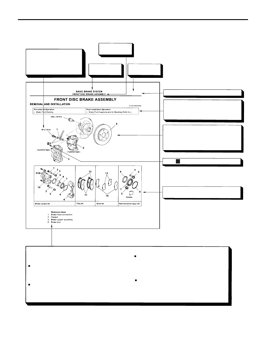
EXPLANATION OF MANUAL CONTENTS
AC311238
N
Denotes tightening torque.
For bolts and nuts which do
not have a tightening torque
listed, refer to the "Standard
Parts tightening-torque Table"
Indicates the
group title.
Indicates the
section title.
Indicates the
group number.
Indicates the page number.
Indicates procedures to be performed be-
fore the work in that section is started, and
procedures to be performed after the work
in that section is finished.
Component diagram
A diagram of the component parts is pro-
vided near the front of each section in order
to give the reader a better understanding of
the installed condition of component parts.
Mark denotes nonreusable part.
Repair kit or parts sets are shown.
(Only very frequently used parts are shown.)
Removal steps :
The part designation number corresponds to
the number in the illustration to indicate remov-
al steps.
Disassembly steps :
The part designation number corresponds to
the number in the illustration to indicate disas-
sembly steps.
Installation steps :
Specified in case installation is impossible in
reverse order of removal steps. Omitted if
installation is possible in reverse order of re-
moval steps.
Reassembly steps :
Specified in case installation is impossible in
reverse order of removal steps. Omitted if
reassembly is possible in reverse order of dis-
assembly steps.
Maintenance and servicing procedures
The numbers provided within the diagram indicate the
sequence for maintenance and servicing procedures.
AE
>>A<<
>>B<<
35A-19