Mercedes-Benz Sprinter / Dodge Sprinter. Manual - part 390


  Index      Mercedes     Mercedes-Benz Sprinter / Dodge Sprinter - service repair manual 2006 year


Search            


Content   ..  388  389  390  391   ..


Mercedes-Benz Sprinter / Dodge Sprinter. Manual - part 390


NOTE:

The

camshaft

housing

Must

Not

be

machined. Basic bore of the camshaft bearings will
be altered.

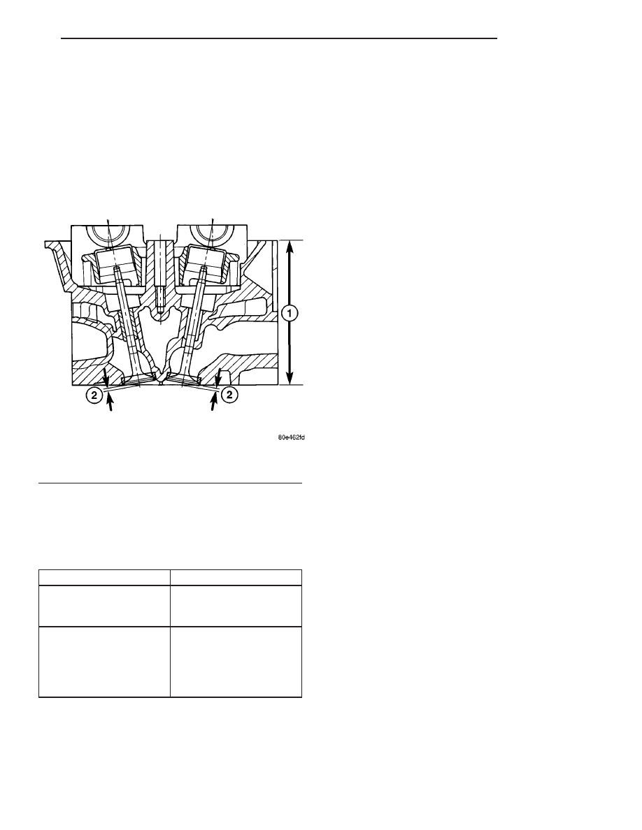
(7) Measure cylinder head height (1) at point indi-

cated, record stock removal (Fig. 13) CYLINDER
HEAD SPECIFICATIONS.

(8) Measure valve setback at points (2) indicated

(Fig. 13) CYLINDER HEAD SPECIFICATIONS.

NOTE: If measurement is less than dimension “2”
no further correct valve clearance compensation is
possible; replace the cylinder head.

CYLINDER HEAD SPECIFICATIONS

Description

Specification

Height of Cylinder Head
(1), With Out Camshaft
Housing

126.85mm to 127.15mm

Valve Set Back (2) With
New Valves and New
Valve Seat Rings

Exhaust Valve: 1.0mm -

1.4mm

Intake Valve: 1.1mm -

1.5mm

REMOVAL

REMOVAL - CYLINDER HEAD

(1) Disconnect negative battery cable.
(2) Position piston of cylinder #1 to ignition TDC.

(3) Raise and support vehicle.
(4) Install retaining lock # 8932 for crankshaft/

starter ring gear.

WARNING: RISK OF INJURY TO SKIN AND EYES
FROM SCALDING COOLANT. DO NOT OPEN COOL-
ING SYSTEM UNLESS TEMPERATURE IS BELOW
90°C (194°F). OPEN CAP SLOWLY TO RELEASE
PRESSURE. STORE COOLANT IN APPROVED CON-
TAINER

ONLY.

WEAR

PROTECTIVE

GLOVES,

CLOTHING AND EYE WEAR.

(5) Drain cooling system at radiator and crankcase

(Refer to 7 - COOLING/ENGINE/COOLANT - STAN-
DARD PROCEDURE).

(6) Loosen the lower turbo support bracket bolt.
(7) Remove the upper support bracket bolt.
(8) Loosen the fasteners retaining the exhaust pipe

to the support bracket at the rear of the engine.

(9) Lower vehicle.
(10) Remove engine cover. (Refer to 9 - ENGINE

COVER- REMOVAL).

(11) Remove camshafts (Refer to 9 - ENGINE/CYL-

INDER HEAD/CAMSHAFT(S) - REMOVAL).

Fig. 13 Cylinder Head Measurments

1 - CYLINDER HEAD HEIGHT
2 - VALVE SETBACK

VA

ENGINE

9 - 23

(12) Remove the camshaft housing at the cylinder

head (Fig. 14).

(13) Remove the high pressure pump.
(14) Remove the front head cover plate.

WARNING: NO FIRE, OPEN FLAMES OR SMOKING.
RISK OF POISONING FROM INHALING AND SWAL-
LOWING FUEL. RISK OF INJURY FROM SKIN AND
EYE CONTACT WITH FUEL. POUR FUELS ONLY
INTO SUITABLE AND APPROPRIATELY MARKED
CONTAINERS.

WEAR

PROTECTIVE

CLOTHING

WHEN HANDLING FUEL.

(15) Remove the high pressure fuel pump interme-

diate gear (Fig. 14).

(16) Disconnect the engine side of the engine har-

ness and set aside.

(17) Disconnect the charge air pipe at the cylinder

head and set aside with the engine harness con-
nected.

(18) Remove the turbocharger oil supply line at

the cylinder head and turbocharger (Fig. 14).

(19) Disconnect the turbocharger at the exhaust

manifold (Fig. 14).

(20) Unbolt the transmission oil level indicator

tube fasteners from the cylinder head and engine
block (Fig. 14).

(21) Disconnect the upper radiator hose and by

pass hose at the thermostat housing (Fig. 14).

NOTE: Capture any fuel spillage when disconnect-
ing fuel lines.

(22) Disconnect the fuel line at the rear of the fuel

rail (Fig. 14).

Fig. 14 CAMSHAFT HOUSING

1 - CAMSHAFT HOUSING

9 - HIGH PRESSURE PUMP INTERMEDIATE GEAR

2 - DOWEL

10 - EXHAUST MANIFOLD

3 - FUEL PIPE

11 - COOLANT PIPE

4 - O-RING

12 - TURBOCHARGER

5 - COOLANT HOSE

13 - O-RING

6 - COOLANT HOSE

14 - TURBOCHARGER OIL SUPPLY LINE

7 - BOLT

15 - BANJO BOLT

8 - BUSHING

16 - TAPPET

9 - 24

ENGINE

VA

(23) Remove upper timing case to cylinder head

bolts (Fig. 15).

NOTE: Loosen cylinder head bolts in the reverse
order of the tightening sequence.

(24) Remove cylinder head bolts and inspect (Refer

to 9 - ENGINE/CYLINDER HEAD - STANDARD
PROCEDURE).

(25) Remove cylinder head (Fig. 15).

NOTE: Carefully clean all mating surfaces and bolt
thread holes. Assure that no oil or grease is present
during reassembly.

(26) Clean all mating surfaces and blow out bolt

thread holes.

REMOVAL - CYLINDER HEAD FRONT COVER

(1) Disconnect negative battery cable.
(2) Remove engine cover (Refer to 9 - ENGINE -

REMOVAL).

(3) Remove cylinder head cover (Refer to 9 -

ENGINE/CYLINDER

HEAD/CYLINDER

HEAD

COVER(S) - REMOVAL).

(4) Remove timing chain tensioner (Refer to 9 -

ENGINE/VALVE

TIMING/TMNG

BELT/CHAIN

TENSIONER&PULLEY - REMOVAL).

WARNING: NO FIRE, OPEN FLAMES OR SMOKING.
SERVICE VEHICLE IN WELL VENTILATED AREAS
AND AVOID IGNITION SOURCES. RISK OF POISON-
ING FROM INHALING AND SWALLOWING FUEL.
RISK OF INJURY FROM SKIN AND EYE CONTACT
WITH FUEL. POUR FUELS ONLY INTO SUITABLE
AND

APPROPRIATELY

MARKED

CONTAINERS.

WEAR PROTECTIVE CLOTHING WHEN HANDLING
FUEL.

(5) Remove vacuum pump (Refer to 9 - ENGINE/

ENGINE BLOCK/INTERNAL VACUUM PUMP -
REMOVAL).

(6) Remove bolts attaching front cover.

NOTE: Lower portion of front cover is sealed with
RTV sealant. Carefully tug at front cover until it
loosens from cylinder head.

(7) Raise locking pawl of top guide rail and remove

cylinder head front cover (Fig. 16).

NOTE: Dowel pins are use as a guide during
assembly and must remain in the proper position to
assure a good sealing surface.

Fig. 15 CYLINDER HEAD

1 - CYLINDER HEAD BOLT
2 - CYLINDER HEAD
3 - DOWEL

4 - GASKET
5 - BOLT TO TIMING COVER

VA

ENGINE

9 - 25

REMOVAL - CYLINDER HEAD GUIDE RAIL

(1) Disconnect negative battery cable.

CAUTION: Rotate engine at crankshaft only. DO
NOT rotate the engine with the bolt of the camshaft
sprocket. DO NOT rotate the engine back.

NOTE: Markings on the camshaft and camshaft
bearing cap must be aligned.

(2) Position piston of number 1 cylinder to ignition

TDC.

(3) Remove engine cover. (Refer to 9 - ENGINE/

CYLINDER HEAD/CYLINDER HEAD COVER(S) -
REMOVAL).

(4) Remove timing chain tensioner (Refer to 9 -

ENGINE/VALVE

TIMING/TIMING

BELT/CHAIN

AND SPROCKETS - REMOVAL).

(5) Carefully raise locking pawl of top slide rail

and remove front cover at cylinder head (Fig. 16).

(6) Insert a locking pin through 1st camshaft bear-

ing cap into the hole in the inlet camshaft sprocket.

(7) Counter hold the camshaft with an open end

wrench to avoid damage and unbolt driver of inlet
camshaft sprocket.

(8) Remove top guide rail.

INSTALLATION

INSTALLATION - CYLINDER HEAD

WARNING: (Refer to 14 - FUEL SYSTEM - WARN-
ING)

NOTE: Thoroughly clean all mating surfaces with
appropriate solvents and blow out bolt holes, to
assure that no grease or oil is present during reas-
sembly. If piston or connecting rods have been
replaced, measure piston protrusion. Inspect all cyl-
inder head bolts for defects and stretching before
installation (Refer to 9 - ENGINE/CYLINDER HEAD -
STANDARD PROCEDURE). Inspect facing cylinder
head contact surface.

(1) Position the cylinder head and gasket properly

on engine using the dowel pins as a guide (Fig. 15).

CAUTION: The M12 cylinder head bolts must be
torqued in 3 stages.

NOTE: Add a small amount of clean engine oil to
the cylinder head bolt threads prior to installation.

Fig. 16 CYLINDER HEAD FRONT COVER

1 - TOP GUIDE RAIL
2 - CYLINDER HEAD COVER
3 - LOCKING PAWL
4 - DOWEL PIN

5 - CYLINDER HEAD FRONT COVER
6 - SEAL
7 - TIMING CHAIN TENSIONER
8 - VACUUM PUMP

9 - 26

ENGINE

VA


Content   ..  388  389  390  391   ..