Mazda Training manual - part 290


  Index      Mazda     Mazda Training Manual


Search            


Content   ..  288  289  290  291   ..


Mazda Training manual - part 290


AIR CONDITIONING 
SG02 - Control System [Manual Air Conditioning]


SG02-11

TC070-15-01H

 
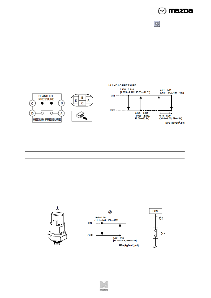
Refrigerant pressure switch 
 
The figure below shows a triple pressure type refrigerant pressure switch that 
consists of the low/high-pressure switch and the medium-pressure switch. The 
low/high-pressure switch protects the refrigerant cycle by cutting the A/C signal when 
pressure in the refrigerant cycle is either abnormally high or low. The medium-
pressure switch outputs an idling increase signal according to the A/C compressor 
operation load. 


Why do you think the system needs to cut the A/C signal when pressure in the 
refrigerant cycle is abnormally low? How does it affect the system?  


Medium-pressure switch operates when the refrigerant pressure is approx. 1.52 kPa 
{14.2 kgf·cm2, 202 psi} or more. When it operates, the contact is closed to send an 
“Idling increase signal” to the PCM. When the A/C is on and an Idling increase signal 
is input to the PCM, it sends an operation signal to the IAC solenoid valve. 


AIR CONDITIONING 
SG02 - Control System [Manual Air Conditioning]


SG02-12

TC070-15-01H

 
Fan switch 
 
The diagram of fan switch is shown in the figure below. Its function can be verified by 
checking the continuity between the terminals at a given status of switch position as 
shown in the table below.     


Climate control unit 
 
A wire-type climate control unit is used with the manual air conditioner. 


1. Airflow mode wire 
2. Air mix wire 
3. Air intake wire 
4. Illumination bulb 
5. Dial 
6. Knob 
7. Fan switch 
8. Body 

AIR CONDITIONING 
SG02 - Control System [Manual Air Conditioning]


SG02-13

TC070-15-01H

 
The airflow mode selector dial, temperature control dial, airflow volume control dial 
have been enlarged to improve ease of operation. 


1. Climate control unit 
2. Airflow mode selector dial 
3. Airflow volume control dial 
4. Temperature control dial 
5. A/C switch 
6. REC/FRESH switch 
7. Rear window defroster switch 


Block Diagram 
 
The climate control unit sends an A/C signal to the PCM via the main fuse and 
instrument cluster (PJB and instrument cluster) based on signals sent from the A/C 
switch, fan switch and evaporator temperature sensor. 
The PCM sends operating signals to the A/C relay and IAC valve based on A/C 
signal and vehicle signal. 


AIR CONDITIONING 
SG02 - Control System [Manual Air Conditioning]


SG02-14

TC070-15-01H

 
Outline of Control System 
 
Manual air conditioner defroster control and A/C compressor control. 


Defroster Control 
 
1. When the airflow mode selector dial is turned to DEFROSTER position, a wire 

moves the airflow mode main link, turning the airflow mode to DEFROSTER. 

2. The defroster switch turns on at the same time, and the CPU sends a signal to turn 

the air intake mode to FRESH. 

3. The air intake actuator operates and turns the air intake mode to FRESH. 


1. Climate control unit 
2. Airflow mode selector 
dial 
3. To DEFROSTER 
position 
4. Defroster switch 
5. Wire 
6. Airflow mode main link 
7. FRESH signal 
8. Air intake actuator 
9. To FRESH position 


Content   ..  288  289  290  291   ..