Mazda Training manual - part 237


  Index      Mazda     Mazda Training Manual


Search            


Content   ..  235  236  237  238   ..


Mazda Training manual - part 237


3 – SHORT BLOCK 


33

Piston Engine Fundamentals

TC010-05-01S

5.    The gap between the main bearings and the main journals is called 
_____________________ . 


6.    The _____________________ half of the crankshaft main bearing has oil holes and fits 
into the ___________________ . 


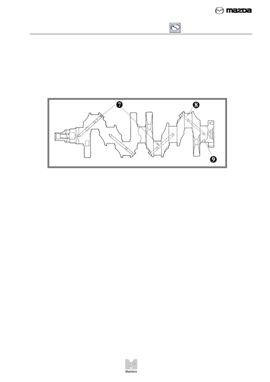
Match the numbered items on the crankshaft drawing to the definitions below.


7.  _______ 

A. 

main journal 


8.  _______ 

B. 

oil passages 


9.  _______ 

C. 

crankpin 


10. Which of these symptoms would you expect to find in an engine that has worn main 
bearings? More than one answer may be correct. 
A.  low oil pressure  
B.  leaking gasoline  
C.  hard starting 
D.    low rattle noise from engine 

 
3 – SHORT BLOCK 


34

Piston Engine Fundamentals

TC010-05-01S


FIGURE 21. The 
connecting rod is 
attached to the 
piston with a 
piston pin.


Piston pin


Bushing


Connecting 
rod


Connecting 
rod bearing 
cap


Upper 
connecting 
rod bearing


Lower 
connecting 
rod bearing


Oil holes


Bearing cap 
nut


Bearing cap 
bolt


CONNECTING RODS


The connecting rod transfers the movement of the piston to the crankpin 
on the crankshaft. Figure 21 shows the connecting rod and its related 
parts. 


A steel piston pin (commonly called the wrist pin) connects the piston to 
the rod. The pin slips through the piston and through the bushing (a 
circular, sleeve-type bearing) in the connecting rod. The pin must be free 
to turn either in the piston or the connecting rod so the rod can rock back 
and forth as the crankshaft turns. In some engines, the pin turns freely in 
both the piston and the connecting rod. Some pins have retainers at both 
ends to keep the pins from sliding out. 


The large end of the connecting rod is connected to the crankshaft with a 
connecting rod bearing cap. 

This cap is very similar to the main bearing 

caps, and the clearances are equally important. 


3 – SHORT BLOCK 


35

Piston Engine Fundamentals

TC010-05-01S

Construction


Connecting rods must be very strong and rigid to handle the force of the 
piston on the power stroke. Connecting rods are usually made of 
high-strength steel, with an “I” construction for extra rigidity. The rods are 
kept as light as possible, and weight variation among the rods is carefully 
controlled so the engine will be balanced. 


Like the main bearings, the connecting rod bearing surfaces are 
line-bored. They must be reinstalled in the same positions from which 
they were removed. If they are not, it can cause premature and 
uneven wear. 

Usually, both the rod and cap are stamped to ensure 

proper reassembly. 


Cylinder Wall Lubrication


As shown in Figure 22, an oil jet in the connecting rod lubricates the 
cylinder walls and cools the piston. The crankshaft oil passages deliver oil 
to the connecting rod journals. When the bearing holes match up with the 
oil hole in the connecting rod journal, pressurized oil is squirted through 
the oil jet. 


Answers to 
Review 
Exercise 3 
 
1.   cylinder 

block 

 
2.   main bearing 

caps


3.   crankshaft


4.      thrust 

bearing


5.   bearing 

clearance


6.   upper; 

cylinder 
block’s main 
support


7.      B


8.      C


9.      A


10.  A and D 


FIGURE 22. The 
oil jet on the 
connecting rod 
squirts oil onto 
the cylinder wall. 
 

Connecting 
rod 

Oil holes 

Upper 
connecting 
rod bearing 

Lower 
connecting 
rod bearing 

Oil jet 


3 – SHORT BLOCK 


36

Piston Engine Fundamentals

TC010-05-01S


FIGURE 23. The 
piston forms the 
bottom of the 
combustion 
chamber.


Head


Piston pin 
bore


Piston ring 
grooves


Thrust 
surface


“ Front” 
mark


Center of 
piston


Center of 
piston pin 
bore 

Offset 

Skirt 

PISTONS


The piston forms the bottom of the combustion chamber in the cylinder. It 
transfers the power created by the burning air-fuel mixture to the 
crankshaft. Figure 23 shows a typical piston. 


The top surface of the piston is called the head, or crown. The upper part 
of the piston contains several grooves where the piston rings fit. The 
lower part of the piston, under the rings, is called the skirt. Thrust 
surfaces 

on the skirt guide the piston in the cylinder bore and prevent the 

piston from rocking back and forth in the cylinder. Most pistons have a 
mark on one side that identifies the side of the piston that faces the front 
of the engine. 


The piston pin bore is drilled through the piston. The piston pin is 
inserted through this bore to attach the piston to the connecting rod. In 
some piston designs, the pin bore is offset slightly from the center of the 
piston. The offset — usually no more than a few thousandths of an inch 
or 0.5-2 millimeters — helps keep the piston from “slapping” against the 
cylinder walls during the power stroke. 


Content   ..  235  236  237  238   ..