Mazda engine MZR–CD. Manual - part 11


  Index      Mazda     Mazda engine MZR–CD - service manual 2002 year


Search            


Content   ..  9  10  11  12   ..


Mazda engine MZR–CD. Manual - part 11


B–24

ENGINE 

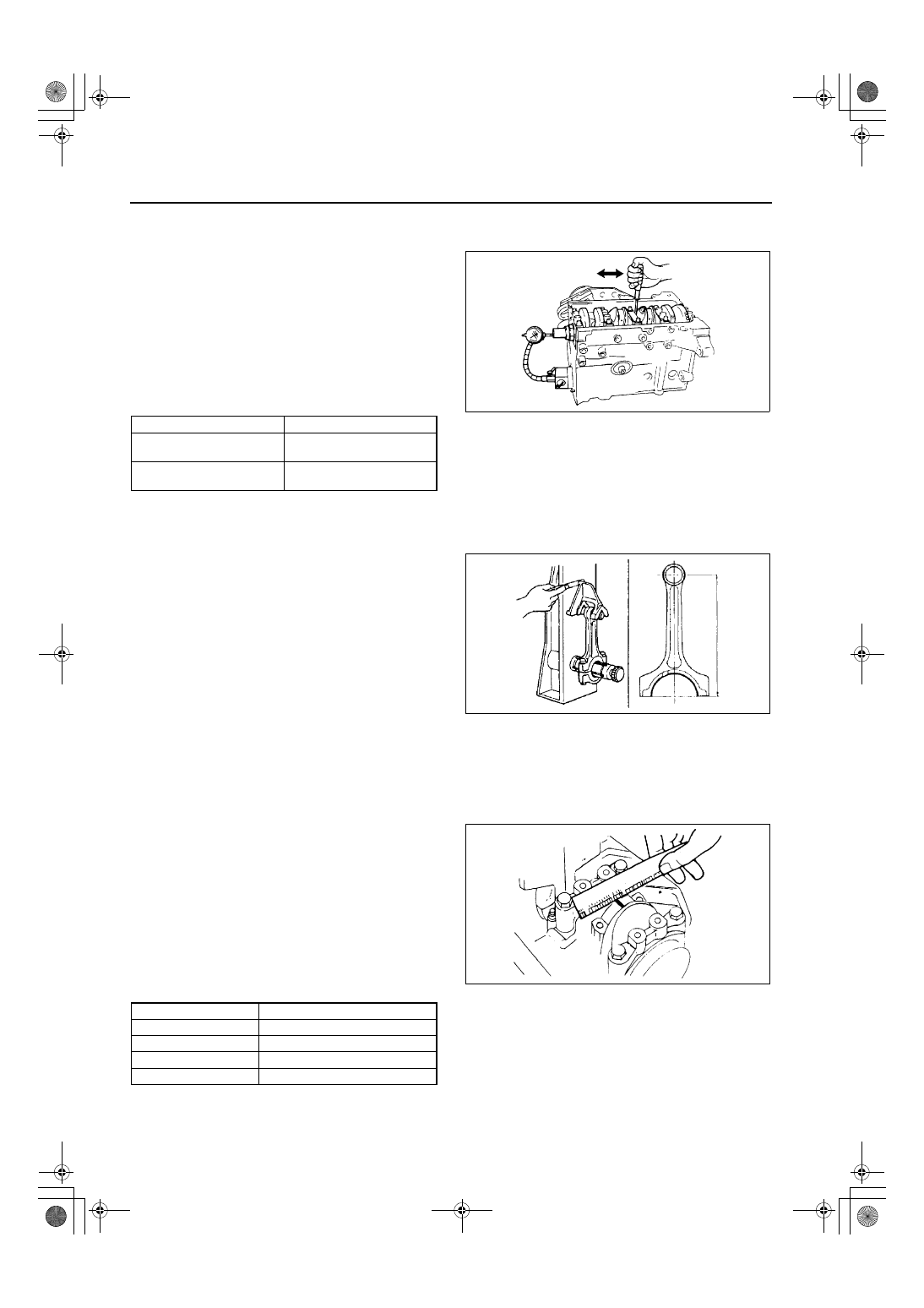
CRANKSHAFT END PLAY INSPECTION/REPAIR

AME222411301103

1. Install the main bearing cap. (See 

B–31 Main Bearing Cap Assembly Note

)

2. Measure the crankshaft end play. If the end play 

exceeds the maximum, replace the thrust bearing 
or grind the crankshaft, and install an undersize 
bearing so that the specified end play is obtained.

Standard end play

0.040—0.282 mm {0.00158—0.01110 in}

Maximum end play

0.30 mm {0.012 in}

(mm {in})

3. Remove the main bearing cap. (See 

B–14 Main Bearing Cap Disassembly Note

)

End Of Sie

CONNECTING ROD INSPECTION

AME222411211101

Measure bending and distortion for each 
connecting rod. Replace the connecting rod if 
necessary.

Bending

0.080 mm {0.0031 in} max. /50 mm {2.0 in}

Distortion 

0.080 mm {0.0031 in} max. /50 mm {2.0 in}

Center-to-center distance 

151.95—152.05 mm {5.983—5.986 in}

End Of Sie

CONNECTING ROD OIL CLEARANCE INSPECTION/REPAIR

AME222411211102

1. Position a plastigage above the journals in the axial direction.
2. Install the connecting rod cap. (See 

B–32 Connecting Rod Cap Assembly Note

)

3. Remove the connecting rod cap.
4. Measure the crankpin oil clearance. If the 

clearance exceeds the maximum, replace the 
connecting rod bearing or grind the crankpin and 
use undersize bearings so that the specified 
clearance is obtained.

Standard clearance

0.027—0.055 mm {0.0011—0.0021in}

Maximum clearance

0.10 mm {0.0039 in}

(mm {in})

End Of Sie

Bearing size

Bearing thickness

Standard

2.00—2.05

{0.0788—0.0807}

0.35 {0.01} oversize

2.175—2.225 

{0.0857—0.0876}

AME2524E050

AME2524E051

Bearing size

Bearing thickness

Standard

1.506—1.515{0.0593—0.0596}

0.25 {0.01} oversize

1.630—1.640{0.0642—0.0645}

0.50 {0.02} oversize

1.755—1.765{0.0691—0.0694}

0.75 {0.03} oversize

1.880—1.890{0.0741—0.0744}

AME2524E052

ENGINE 

B–25

B

CONNECTING ROD SIDE CLEARANCE INSPECTION

AME222411211103

1. Install the connecting rod cap. (See 

B–32 Connecting Rod Cap Assembly Note

)

2. Measure the connecting rod large end side 

clearance. Replace the connecting rod and cap if 
necessary.

Standard clearance

0.110—0.262 mm {0.0044—0.0103 in}

Maximum clearance

0.512 mm {0.0202 in}

3. Remove the connecting rod cap.

End Of Sie

PISTON AND CONNECTING ROD INSPECTION

AME222411010106

Insert the oscillation torque as shown.
If the large end does not drop by its own weight, 
replace the piston or the piston pin.

End Of Sie

CYLINDER HEAD BOLT INSPECTION

AME222410100102

Measure the length of each connecting rod bolt. 
Replace if necessary.

Maximum length

161.0 mm {6.338 in}

End Of Sie

AME2524E053

AME2524E054

AME2524E055

B–26

ENGINE 

TIMING BELT AUTO TENSIONER INSPECTION

AME222412711102

1. Measure the tensioner rod projection length.
2. Inspect the auto tensioner for oil leakage.

Replace the auto tensioner if necessary.

Projection (Free length)
 12.9—14.6 mm {0.508—0.574 in}

3. Inspect for the resistance of the auto tensioner 

rod, when it is pushed with a force of 
approximately 235 N {24 kgf, 53 lbf}.
If there is no resistance on the tensioner rod is not 
resistance and it moves slightly, perform the 
following procedure.

Caution

••••

To prevent damage to the inside of the 
auto tensioner, do not press down the 
auto tensioner rod with a force greater 
than the specified 235 N {24 kgf, 53 lbf}. 
Be careful that the rod does not touch the 
bottom.

(1) Push it down slowly two or three times to the bottom end of the end.
(2) When the rod protrudes approximately 8.1 mm {0.32 in}, verify that the resistance is restored on the 

tensioner rod.
If the resistance is not restored, replace the auto tensioner.

End Of Sie

PILOT BEARING INSPECTION

AME222411501101

Verify that the pilot bearing rotates smoothly without any abnormal noise. Replace if necessary.

Replacement

1. Remove the pilot bearing from the crankshaft 

using the SST.

2. Install the pilot bearing using the SSTs.

End Of Sie

AME2524E056

AME2524E080

AME2524E081

ENGINE 

B–27

B

OIL PUMP INSPECTION

AME222419220101

Relief Spring

Measure the free length of the relief spring. 
Replace the relief spring if necessary.

Free length

43.8 mm {1.724 in}

Rotor Clearance

Measure the following clearances. Replace the 
rotor if necessary.

Tooth tip clearance

0.030—0.120 mm {0.0012—0.0047 in}

Maximum tip clearance

0.16 mm {0.006 in}

Outer rotor-to-pump body clearance

0.200—0.294 mm {0.0079—0.0115 in}

Maximum clearance

0.35 mm {0.013 in}

Side clearance

 0.040—0.100 mm {0.0016—0.0039 in}

 Maximum clearance

 0.15 mm {0.0059 in}

End Of Sie

AME2524E057

AME2524E058

AME2524E059

AME2524E060


Content   ..  9  10  11  12   ..