Mazda Engine LF, L3. Manual - part 13


  Index      Mazda     Mazda Engine LF, L3 - service repair manual 2005 year


Search            


Content   ..  11  12  13  14   ..


Mazda Engine LF, L3. Manual - part 13


MECHANICAL 

01–10–35

01–10

Engine Workshop Manual LF L3 (1866–1U–05H)

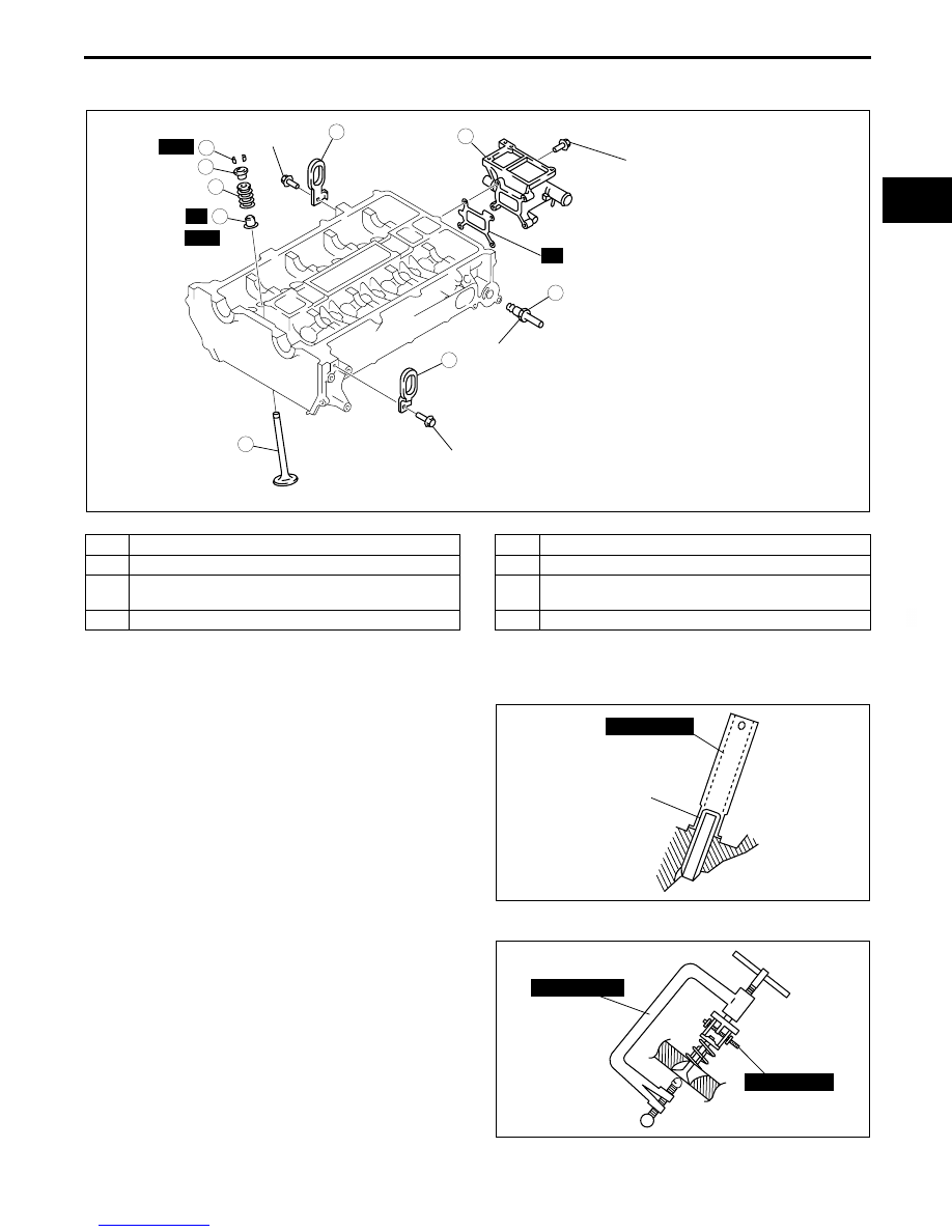
CYLINDER HEAD (I) ASSEMBLY

E5U011002000E10

1. Assemble in the order indicated in the table.

.

Valve Seal Assembly Note

1. Press the valve seal onto the valve guide by hand.
2. Lightly tap the SST using a plastic hammer.

Valve Keeper Assembly Note

1. Install the valve keeper using the SSTs.

End Of Sie

8

8

7

5

4

3

1

2

6

SST

SST

R

R

42—48 {4.3—4.8, 
31.0—35.4}

42—48 {4.3—4.8, 31.0—35.4}

56—60 {5.8—6.1, 
41.3—44.2}

8.0—11.5 N·m {81.6—117.2 
kgf·cm, 70.9—101.7 in·lbf}

N·m {kgf·m, ft·lbf}

B3E0110E130

1

Water outlet

2

EGR pipe

3

Valve seal
(See 01–10–35 Valve Seal Assembly Note)

4

Valve

5

Valve  spring

6

Upper valve spring seat

7

Valve keeper
(See 01–10–35 Valve Keeper Assembly Note)

8

Engine hanger

VALVE 
SEAL

49 T032  302

B3E0110E123

49 B012 0A2

49 0636 100B

B3E0110E124

MECHANICAL 

01–10–36

Engine Workshop Manual LF L3 (1866–1U–05H)

Revised 12/2005 (Ref. No. R145/05)

CYLINDER HEAD (II) ASSEMBLY

E5U011002000E11

1. Assemble in the order indicated in the table.

.

1

2

3

5

6

6

8

7

5

7

R

4

5.0—9.0 N·m 
{51.0—91.7 kgf·cm, 
44.3—79.5 in·lbf}+ 
14—17

3—11 
{30.6—112 kgf·cm, 
26.6—97.3 in·lbf}+

13—17 {1.4—1.7, 9.6—12.5}+
43—47 {4.4—4.7, 31.8—34.6}+
88

°—92°+

88

°—92° 

{1.43—1.73, 
10.4—12.5}

N·m {kgf·m, ft·lbf}

SST

8.0

11.5 

N·m 

{81.5—117 kgf·cm 
70.8—101in·lbf}

5.0—9.0 N·m 
{51.0—91.7 kgf·cm, 
44.3—79.5 in·lbf}+ 
14—17
{1.43—1.73, 
10.4—12.5}

R

R

R

WITH VARIABLE VALVE TIMING MECHANISM 

*

*

*

*: IF WASHER IS NOT INSTALLED TO THE ENGINE, INSTALL A NEW WASHER.

E5U110ZECL02

1

Cylinder head gasket

2

Cylinder head

3

Cylinder head bolt
(See 01–10–37 Cylinder Head Bolt Assembly Note)

4

Tappet

5

Camshaft
(See 01–10–37 Camshaft Assembly Note)

6

Camshaft cap 

7

Camshaft sprocket, variable valve timing actuator 
(See 01–10–37 Camshaft Sprocket, Variable Valve 
Timing Actuator Assembly Note)

8

Oil control valve (OCV) (With variable valve timing 
mechanism)

MECHANICAL 

01–10–37

01–10

Cylinder Head Bolt Assembly Note

1. Tighten the cylinder head bolts in the order 

indicated in the figure in 5 steps using the SST 
(49 D032 316)
.

Tightening torque

(1) 3—11 N·m

{30.6—112 kgf·cm, 26.6—97.3 in·lbf}

(2) 13—17 N·m

{1.4—1.7 kgf·m, 9.6—12.5 ft·lbf}

(3) 43—47 N·m

{4.4—4.7 kgf·m, 31.8—34.6 ft·lbf}

(4) 88

°—92°

(5) 88

°—92°

Camshaft Assembly Note

1. Set the cam position of No.1 cylinder at the top dead center (TDC) and install the camshaft.
2. Temporarily tighten the camshaft bearing caps evenly in 2—3 steps.
3. Tighten the camshaft cap bolt in the order shown 

two steps.

Tightening torque

(1) 5.0—9.0 N·m

{51.0—91.7 kgf·cm, 44.3—79.5 in·lbf}

(2) 14—17 N·m

{1.43—1.73 kgf·m, 10.4—12.5 ft·lbf}

Camshaft Sprocket, Variable Valve Timing Actuator Assembly Note

1. Temporarily tighten the camshaft sprocket or variable valve timing actuator installation bolts by hand until the 

timing chain is installed.

2. Fully tighten the camshaft sprocket or variable valve timing actuator installation bolts after timing chain 

installation.

End Of Sie

9

8

7

4

3

1

2

10

5

6

C3U0110E054

9

8

7

5

4

3

1

2

10

19

18

17

15

16

14

13

11

12

20

6

B3E0110E098

MECHANICAL 

01–10–38

TIMING CHAIN ASSEMBLY

E5U011002000E12

1. Assemble in the order indicated in the table.

.

SEALANT

SEALANT

SEALANT

SEALANT

OIL

SEALANT

A

A

A

A

N·m {kgf·m, ft·lbf}

SST

SST

SST

R

R

R

R

20—30 
{2.1—3.0, 
14.8—22.1}

20—30 
{2.1—3.0, 
14.8—22.1}

20—30 
{2.1—3.0, 
14.8—22.1}

40—55 
{4.1—5.6, 
29.6—40.5}

8.0—10.5 N·m 
{81.6—107.1 kgf·cm, 
70.9—92.9 in·lbf}

8.0—11.5 N·m 
{81.6—117.2 kgf·cm, 
70.9—101.7 in·lbf}

96—104  
{9.8—10.6, 
70.9—76.7}+
87

°—93°

69—75  {7.1—7.6, 50.9—55.3}

:

9

8

7

5

4

3

1

2

10

19

18

17

15

16

14

13

11

12

6

11

69—75  {7.1—7.6, 50.9—55.3}

SST

40—55 
{4.1—5.6,
29.6—40.5}

WITHOUT 
A/C

20

WITH VARIABLE VALVE TIMING 
MECHANISM

E5U110ZE7S05

1

Crankshaft sprocket

2

Oil pump chain

3

Oil pump sprocket
(See 01–10–39 Oil Pump Sprocket Assembly Note.)

4

Oil pump chain guide

5

Oil pump chain tensioner

6

Seal (With variable valve timing mechanism)

7

Timing chain
(See 01–10–39 Timing Chain Assembly Note.)

8

Chain guide

9

Tensioner arm

10

Chain tensioner

11

Camshaft sprocket, variable valve timing actuator 
(See 01–10–40 Camshaft Sprocket, Variable Valve 
Timing Actuator Assembly Note.)

12

Engine front cover
(See 01–10–41 Engine Front Cover Assembly 
Note.)

13

Front oil seal
(See 01–10–40 Front Oil Seal Assembly Note.)

14

Drive belt idler pulley (Without stretch-type A/C drive 
belt)

15

Water pump pulley

16

Crankshaft pulley

17

Crankshaft pulley lock bolt
(See 01–10–41 Crankshaft Pulley Lock Bolt 
Assembly Note.)

18

Cylinder head cover
(See 01–10–42 Cylinder Head Cover Assembly 
Note)

19

Spark plug

20

Dipstick (if equipped)


Content   ..  11  12  13  14   ..