Mazda Engine LF, L3. Manual - part 10


  Index      Mazda     Mazda Engine LF, L3 - service repair manual 2005 year


Search            


Content   ..  8  9  10  11   ..


Mazda Engine LF, L3. Manual - part 10


MECHANICAL 

01–10–23

01–10

End Of Sie

VALVE CLEARANCE ADJUSTMENT

E5U011012111E04

1. Remove the engine front cover lower blind plug.
2. Remove the engine front cover upper blind plug.
3. Remove the cylinder block lower blind plug.

4. Install the SST as shown in the figure.

Caution

• Removal of this SST is extremely 

important. If you crank the engine with 
this SST installed, the cylinder block will 
be damaged.

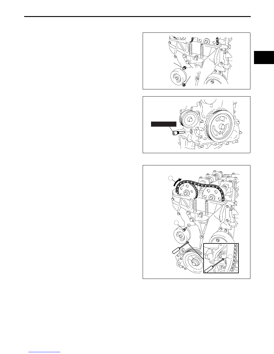
5. Turn the crankshaft clockwise so that the 

crankshaft is in the No.1 cylinder TDC position.

6. Loosen the timing chain.

(1) Using a suitable screwdriver or equivalent 

tool, unlock the chain tensioner ratchet.

(2) Turn the exhaust camshaft clockwise using a 

suitable wrench on the cast hexagon and 
loosen the timing chain.

(3) Placing the suitable bolt (M6 

× 1.0 Length 

25—35 mm {0.9—1.3 in}) at the engine front 
cover upper blind plug, secure the chain guide 
at the position where the tension is released.

UPPER 
BLIND 
PLUG

LOWER BLIND 
PLUG

B3E0110E093

303-507

D3U110ZE4006

3

1

2

BOLT (M6 x 1.0)

B3E0110E096

MECHANICAL 

01–10–24

7. Hold the exhaust camshaft using a suitable 

wrench on the cast hexagon as shown in the 
figure.

8. Remove the exhaust camshaft sprocket.

9. Loosen the camshaft cap bolts in several passes 

in the order shown in the figure.

Note

• The cylinder head and the camshaft caps 

are numbered to make sure they are 
reassembled in their original position. When 
removed, keep the caps with the cylinder 
head they were removed from. Do not mix 
the caps.

10. Remove the camshaft.
11. Remove the tappet.
12. Select proper adjustment shim.

New adjustment shim

= Removed shim thickness + Measured valve clearance - Standard valve clearance (IN: 0.25 mm 

{0.0098 in}, EX: 0.30 mm {0.0118 in})

Valve clearance [Engine cold]

IN: 0.22—0.28 mm {0.0087—0.0110 in}
EX: 0.27—0.33 mm {0.0106—0.0130 in}

13. Install the camshaft with No.1 cylinder aligned with the TDC position.
14. Tighten the camshaft cap bolt using the following 

two steps.

Tightening torque

(1) 5.0—9.0 N·m 

{51.0—91.7 kgf·cm, 44.3—79.5 in·lbf}

(2)14.0—17.0 N·m 

{1.43—1.73 kgf·m, 10.4—12.5 ft·lbf}

B3E0110E095

EXHAUST 
CAMSHAFT 
SPROCKET

B3E0110E097

9

8

7

5

4

3

1

2

10

19

18

17

15

16

14

13

11

12

20

6

B3E0110E057

9

8

7

5

4

3

1

2

10

19

18

17

15

16

14

13

11

12

20

6

B3E0110E098

MECHANICAL 

01–10–25

01–10

Engine Workshop Manual LF L3 (1866–1U–05H)

Revised 12/2005 (Ref. No. R145/05) 

15. Install a new washer. 

16. Install the exhaust camshaft sprocket.

Note

• Do not tighten the bolt for the camshaft 

sprocket during this step. First confirm the 
valve timing, then tighten the bolt.

17. Install the SST to the camshaft as shown in the 

figure.

18. Remove the M6 

× 1.0 bolt from the engine front 

cover to apply tension to the timing chain.

19. Turn the crankshaft clockwise so that the 

crankshaft is in the No.1 cylinder TDC position.

20. Hold the exhaust camshaft using a suitable 

wrench on the cast hexagon as shown in the 
figure.

21. Tighten the exhaust camshaft sprocket lock bolt.

Tightening torque

69—75 N·m {7.1—7.6 kgf·m, 50.9—55.3 ft·lbf}

22. Remove the SST from the camshaft.
23. Remove the SST from the block lower blind plug.
24. Rotate the crankshaft clockwise two turns until 

the TDC position.

• If not aligned, loosen the camshaft sprocket 

lock bolt and repeat from Step 17.

R

D3U110ZE4012

EXHAUST 
CAMSHAFT 
SPROCKET

B3E0110E097

303-465

(49 UN30 3465)

C3U0110E066

B3E0110E095

MECHANICAL 

01–10–26

Engine Workshop Manual LF L3 (1866–1U–05H)

25. Install the new engine front cover upper blind 

plug.

Tightening torque

8.0—11.5 N·m {82—117 kgf·cm, 71—101 

in·lbf}

26. Install the cylinder block lower blind plug.

Tightening torque

18—22 N·m {1.9—2.2 kgf·m, 13.3—16.2 ft·lbf}

27. Install the new engine front cover lower blind plug.

Tightening torque

10—14 N·m {102—142 kgf·cm, 89—123 

in·lbf}

End Of Sie

BLIND 
PLUG

B3E0110E101

BLIND 
PLUG

B3E0110E102

ENGINE FRONT 
COVER LOWER 
BLIND PLUG

B3E0110W063


Content   ..  8  9  10  11   ..