Mazda Transaxle G35M–R. Manual - part 11


  Index      Mazda     Mazda Transaxle G35M–R - service manual 2002 year


Search            


Content   ..  9  10  11  12   ..


Mazda Transaxle G35M–R. Manual - part 11


MANUAL TRANSAXLE 

J–25

J

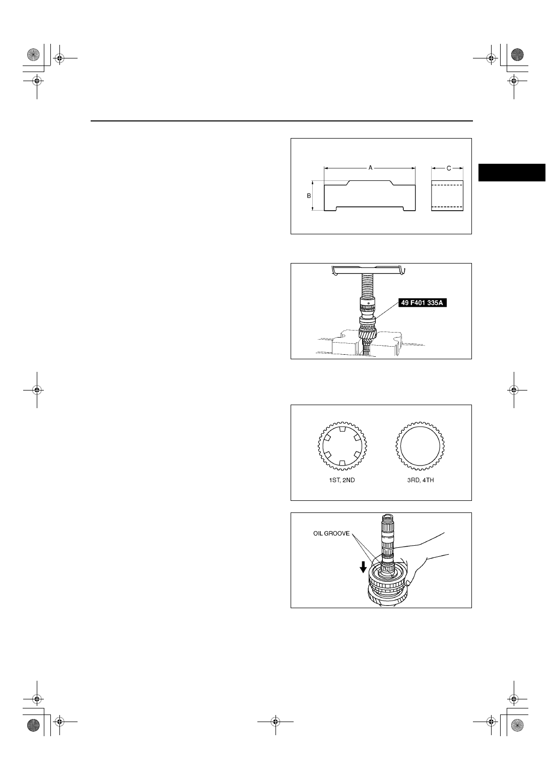
1st/2nd Clutch Hub Assembly Note

1. Install the synchronizer key springs in the clutch 

hub with the hooks in the grooves to hold the 
three synchronizer keys in place.

Synchronizer key

A: 19.0 mm {0.748 in}
B: 4.3 mm {0.17 in}
C: 5.0 mm {0.20 in}

Bearing (Secondary Shaft End) Assembly Note

1. Install the new bearing using the SST.

1st Gear, 1st Synchronizer Ring, and 1st/2nd Clutch Hub Component Assembly Note

Note

The size of the 1st, 2nd, 3rd, and 4th 
synchronizer rings are the same. 

1. Assemble the 1st gear, 1st synchronizer ring, and 

1st/2nd clutch hub component, as shown in the 
figure.

A6E5110M131

Z4F5112M052

A6E5112M114

Z4F5112M054

J–26

MANUAL TRANSAXLE 

2. Press the 1st/2nd clutch hub component on using 

the SST.

2nd Synchronizer Ring, 2nd Gear, and Secondary 3rd Gear Assembly Note

1. Install the 2nd synchronizer ring and 2nd gear.
2. Install the secondary 3rd gear using the SST.

Secondary 4th Gear and Bearing Assembly Note

1. Install the secondary 4th gear and the bearing 

using the SST.

2. Measure the clearance between the 1st gear and 

the differential drive gear.

Clearance

0.05—0.28 mm {0.002—0.011 in}

Maximum

0.33 mm {0.013 in}

Z4F5112M055

A6E5112M115

Z4F5112M057

A6E5112M058

MANUAL TRANSAXLE 

J–27

J

3. Measure the clearance between the 2nd gear and 

the secondary 3rd gear.

If not as specified, reassemble the secondary 
shaft component.

Clearance

0.18—0.46 mm {0.007—0.018 in}

Maximum

0.51 mm {0.020 in}

End Of Sie

DIFFERENTIAL PREINSPECTION

A6E511227100M01

Backlash Inspection

1. Measure the backlash of the side gear.

If not as specified, replace parts as 
necessary.

Standard

0.050—0.150 mm{0.0020—0.059 in}

End Of Sie

A6E5112M059

A6E5112M060

J–28

MANUAL TRANSAXLE 

DIFFERENTIAL DISASSEMBLY

A6E511227100M02

1. Disassemble in the order shown in the figure.

.

Bearing (Side Opposite Ring Gear) Disassembly Note

1. Remove the bearing using the SSTs.

Z4F5112M061

1

Roll pin

2

Pinion shaft

3

Pinion gear

4

Thrust washer

5

Side gear

6

Thrust washer

7

Bearing (side opposite ring gear)
(See 

J–28 Bearing (Side Opposite Ring Gear) 

Disassembly Note

)

8

Speedometer drive gear

9

Bearing (ring gear side)
(See 

J–29 Bearing (Ring Gear Side) Disassembly 

Note

)

10

Ring gear and gear case component

Z4F5112M062


Content   ..  9  10  11  12   ..