Mazda Transaxle A65M–R. Manual - part 10
 

  Index      Mazda     Mazda Transaxle A65M–R - service manual 2002 year


Search            


Content   ..  8  9  10  11   ..


Mazda Transaxle A65M–R. Manual - part 10


MANUAL TRANSAXLE 

J–21

J

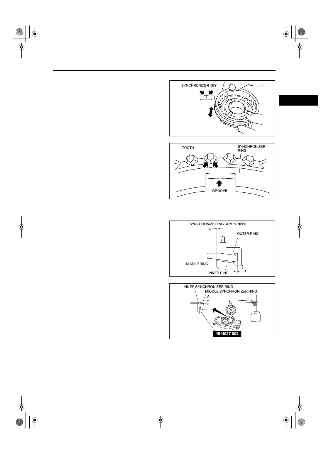
Synchronizer Ring and Clutch Hub Component Inspection

1. Inspect the clutch hub sleeve, clutch hub, and 

synchronizer key contact surface for damage and 
abnormal wear.

•

If there is malfunction, replace the part where 
necessary.

2. Verify that the clutch hub sleeve and clutch hub 

move smoothly.

•

If there is malfunction, replace parts as 
necessary.

3. Inspect the synchronizer ring teeth and grooves 

for damage, abnormal wear, and cracks.

•

If there is malfunction, replace the 
synchronizer ring.

4. Inspect the tapered surface for abnormal wear 

and cracks.

•

If there is malfunction, replace parts as 
necessary.

Synchronizer Ring Clearance Inspection
Synchronizer component (1st gear)

1. Measure the clearance of synchronizer 

component outer, middle and inner synchronizer 
rings.

•

If clearances A and B exceed the maximum, 
replace as a set.

(1) Measure clearance A in two places or more 

and on opposite sides using a dial gauge, and 
calculate the average value.

Clearance A

Standard: 0.60—0.80 mm 

{0.0236—0.0315 in}

Maximum: 0.20 mm {0.0079 in} or less

AME5112M045

AME5112M046

AME5112M059

AME5112M129

J–22

MANUAL TRANSAXLE 

(2) Measure clearance B in two places or more 

and on opposite sides using a feeler gauge, 
and calculate the average value.

Clearance B

Standard: 0.60—1.10 mm 

{0.0236—0.0433 in}

Maximum: 0.20 mm {0.0079 in} or less

Synchronizer component (2nd gear)

1. Inspect clearance of the synchronizer component 

outer, middle, and inner synchronizer rings.

•

If the clearance A, B and C exceed the 
maximum, replace as a set.

(1) Measure clearance A in two places or more 

and on opposite sides using a feeler gauge 
while the synchronizer ring is manually press 
fit to the taper surface of the clutch gear, and 
calculate the average value.

Clearance A

Standard: 0.60—1.20 mm 

{0.0236—0.0472 in}

Maximum: 0.30 mm {0.0118 in} or less

(2) Measure clearance B in two places or more 

and on opposite sides with a feeler gauge, 
and calculate the average value.

Clearance B

Standard: 0.60—1.10 mm 

{0.0236—0.0433 in}

Maximum: 0.20 mm {0.0079 in} or less

AME5112M060

AME5112M092

AME5112M090

AME5112M060

MANUAL TRANSAXLE 

J–23

J

(3) Measure clearance C in two places or more 

and on opposite sides with a feeler gauge 
while the synchronizer ring is manually press 
fit to the taper surface of the clutch gear, and 
calculate the average value.

Clearance C

Standard: 0.70—1.10 mm 

{0.0276—0.0433 in}

Maximum: 0.30 mm {0.0118 in} or less

Bearing Inspection

1. Inspect the ball and the ball contact surface for damage and abnormal wear.

•

If there is malfunction, replace the bearing.

2. Verify that the bearing rotates smoothly.

•

If there is malfunction, replace the bearing.

End Of Sie

AME5112M091

AME5112M072

J–24

MANUAL TRANSAXLE 

SECONDARY SHAFT COMPONENTS ASSEMBLY

AME511217301M04

1. Assemble in the order shown in the figure.

.

AME5112M136

1

Secondary shaft

2

Reverse main gear
(See 

J–25 Reverse Main Gear Assembly Note

)

3

1st bushing
(See 

J–25 1st Bushing Assembly Note

)

4

1st needle bearing

5

1st gear

6

1st inner synchronizer component

7

Synchronizer key spring
(See 

J–26 Synchronizer Key Spring, 1st/2nd 

Synchronizer Key and 1st/2nd Clutch Hub and 
Sleeve Assembly Note

)

8

1st/2nd synchronizer key

9

1st/2nd clutch hub and sleeve

10

1st/2nd clutch hub set
(See 

J–26 1st/2nd Clutch Hub Set Assembly Note

)

11

2nd inner synchronizer component

12

2nd bushing
(See 

J–27 2nd Bushing Assembly Note

)

13

2nd needle bearing

14

2nd gear

15

3rd gear
(See 

J–27 3rd Gear Assembly Note

)

16

3rd/4th secondary shaft spacer

17

4th gear adjustment shim
(See 

J–27 4th Gear Adjustment Shim Assembly 

Note

)

18

4th gear
(See 

J–28 4th Gear Assembly Note

)

19

5th gear
(See 

J–28 5th Gear Assembly Note

)

20

5th gear Snap ring
(See 

J–28 5th Gear Snap Ring Assembly Note

)

21

Secondary shaft rear bearing
(See 

J–28 Secondary Shaft Rear Bearing Assembly 

Note

)

22

Secondary shaft C ring
(See 

J–29 Secondary Shaft C Ring Assembly Note

)

23

C ring holder

24

Snap ring

25

Snap ring

26

Secondary shaft rear bearing adjust shim


Content   ..  8  9  10  11   ..