Mazda Automatic Transaxle JA5A-EL. Manual - part 33
AUTOMATIC TRANSAXLE
K137
K1
12. Remove the SSTs.
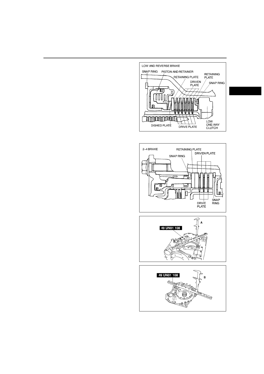
2-4 brake
1. Install the clutch plates, drive and driven plates as
shown in the figure.
2. Using the dial depth gauge and the SST,
measure clearance between the retaining plate
and the snap ring.
Note
• When measuring the 2-4 brake clearance,
do not install the retaining plate in the
transaxle case.
(1) Position the SST on the surface of the
transaxle case where it contacts the end
cover.
(2) Measure the height A between the SST
surface and the driven plate.
(3) Position the SST on the piston edge of the
end cover.
(4) Measure the height B between the SST
surface and the contact surfaces of the end
cover and transaxle case.
(5) Measure the retaining plate thickness C.
(6) Calculate the clearance using the following
formula.
Clearance = A B C
0.6 0.9 mm {0.020.04 in}
AMU0517A092
AMU0517A093
AMU0517A172
AMU0517A171