Mazda CX-9 Grand Touring. Manual - part 133
Master cylinder fluid pressure
MASTER CYLINDER FLUID PRESSURE SPECIFICATION
After-inspection procedure
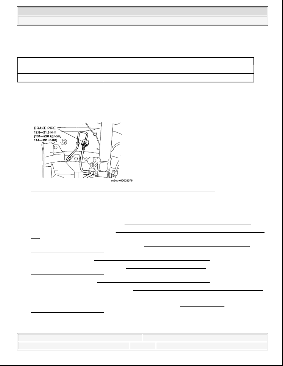
1. After the inspection, remove the SSTs, install the brake hose, clamp, and brake pipe to the original
positions, and then bleed the air from the brake line.
Fig. 18: Identifying Brake Pipe To Original Positions & Torque Specifications
Courtesy of MAZDA MOTORS CORP.
POWER BRAKE UNIT REMOVAL/INSTALLATION
1. Remove the battery and battery tray. (See BATTERY REMOVAL/INSTALLATION [MZI-3.7] .)
2. Remove the resonance chamber. (See INTAKE-AIR SYSTEM REMOVAL/INSTALLATION [MZI-
3.7] .)
3. Remove the windshield wiper arm and blade. (See WINDSHIELD WIPER ARM AND BLADE
REMOVAL/INSTALLATION .)
4. Remove the cowl grill. (See COWL GRILLE REMOVAL/INSTALLATION .)
5. Remove the windshield wiper motor. (See WINDSHIELD WIPER MOTOR
REMOVAL/INSTALLATION .)
6. Remove the cowl panel. (See COWL PANEL REMOVAL/INSTALLATION .)
7. Remove the master cylinder component. (See MASTER CYLINDER REMOVAL/INSTALLATION.)
8. Remove the nuts as shown in the figure, and move the front heater pipe.
9. Remove the brake pipe (DSC/RSC HU/CM-master cylinder). (See DSC/RSC HU/CM
REMOVAL/INSTALLATION .).
Vacuum amount at 66.7 kPa {500 mmHg, 19.7 inHg}
Pedal force (N {kgf, lbf})
Fluid pressure (kPa {kgf/cm
2
, psi})
200 N {20.4 kgf, 44.9 lbt}
9,000 kPa {91.78 kgf/cm
2
, 1,306 psi} or more
2008 Mazda CX-9 Grand Touring
2008 BRAKES Conventional Brake System - Mazda CX-9
Microsoft
Sunday, November 15, 2009 9:48:49 AM
Page 14
© 2005 Mitchell Repair Information Company, LLC.