Mazda CX-9 Grand Touring. Manual - part 118
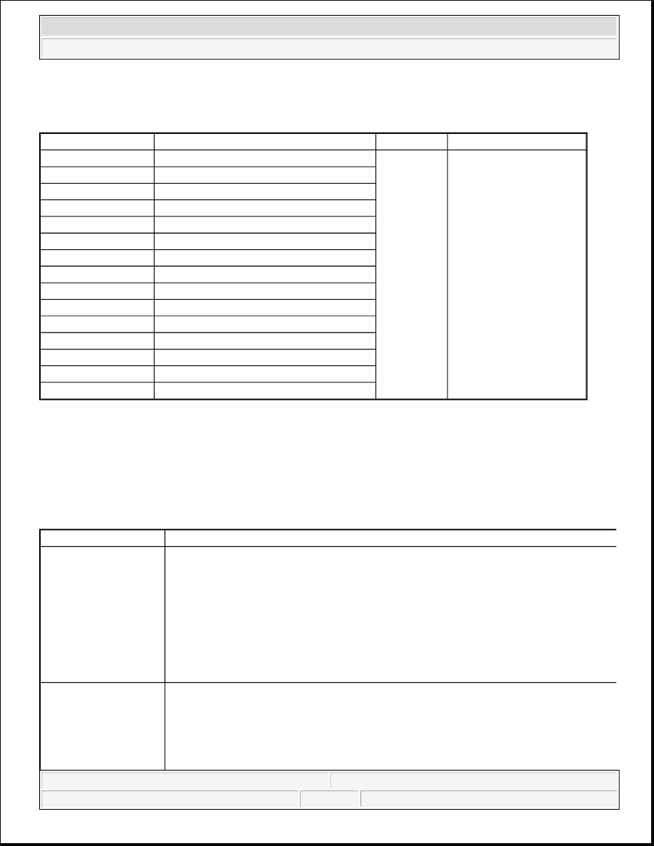
ACTIVE COMMAND MODES TABLE
ACTIVE COMMAND MODES CHART
DTC B1317, B1318 [DSC/RSC]
DTC B1317, B1318 [DSC/RSC] DETECTION CONDITION AND POSSIBLE CAUSE
Command name
Output part
Operation
Operating condition
PMP_MOTOR
Pump motor
Off/On
Ignition switch at ON
PWR_RLY
Valve relay
SSR_INTL
DSC/RSC sensor initialization
V_LF_INL
LF inlet solenoid valve
V_LF_OTL
LF outlet solenoid valve
V_LR_INL
LR inlet solenoid valve
V_LR_OTL
LR outlet solenoid valve
V_RF_INL
RF inlet solenoid valve
V_RF_OTL
RF outlet solenoid valve
V_RR_INL
RR inlet solenoid valve
V_RR_OTL
RR outlet solenoid valve
V_STB_L
LH stability control solenoid valve
V_STB_R
RH stability control solenoid valve
V_TRC_L
LH traction control solenoid valve
V_TRC_R
RH traction control solenoid valve
NOTE:
DTC B1317 is output when the battery voltage is 16 V or more. If DTC
B1317 is output, inspect the battery and charging system for a malfunction
before performing the malfunction diagnosis.
DTC B1317, B1318 Power supply system
DETECTION
CONDITION
B1317
DSC/RSC HU/CM terminal X voltage of 16 V or more continues for 3 s
while driving at a vehicle speed of 8 km/h or more.
DSC/CM terminal X voltage of 18.5 V or more continues for 15 ms while
driving at a vehicle speed of 8 km/h or more.
B1318
DSC/RSC HU/CM terminal X voltage of 10 V or less continues for 3 s
while driving at a vehicle speed of 8 km/h or more.
POSSIBLE CAUSE
SAS 7.5A fuse malfunction
Open circuit or short to ground in the wiring harness between the DSC/RSC
HU/CM terminal X and the battery
Open circuit or faulty ground in the wiring harness between the DSC/RSC
HU/CM terminal A and the body ground
2008 Mazda CX-9 Grand Touring
2008 BRAKES On-Board Diagnostic (DSC/RSC) - Mazda CX-9
Microsoft
Sunday, November 15, 2009 9:50:12 AM
Page 13
© 2005 Mitchell Repair Information Company, LLC.