Mazda CX 7. Manual - part 434


  Index      Mazda     Mazda CX 7 - service repair manual 2007 year


Search            


Content   ..  432  433  434  435   ..


Mazda CX 7. Manual - part 434


INSTRUMENTATION/DRIVER INFO. 

09-22–5

09-22

INSTRUMENT CLUSTER INPUT/OUTPUT CHECK MODE

id092200801700

Note

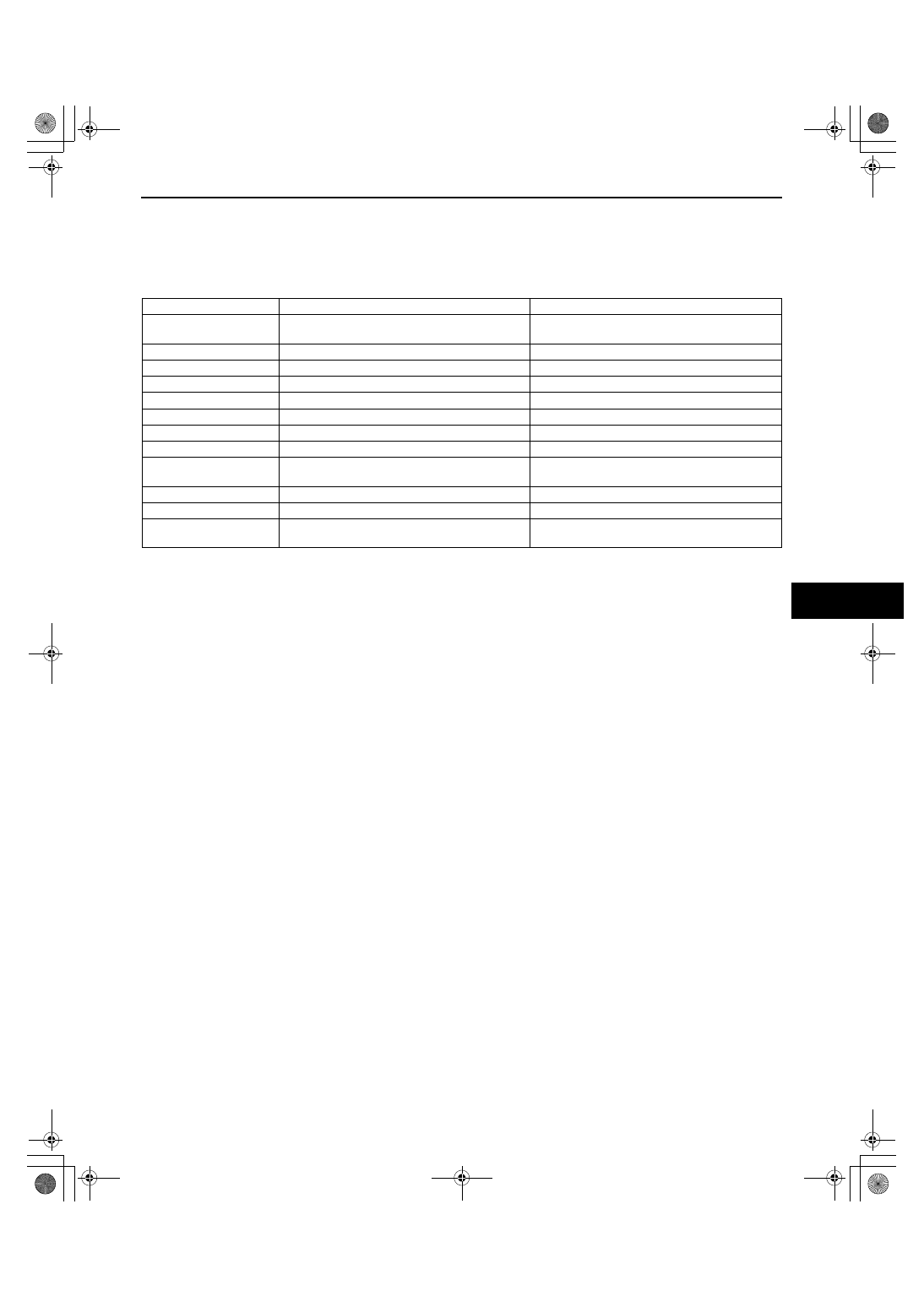
• In this mode, it is possible to verify the items in the following chart.

Check Code Table

Note

• Check codes which are not listed may be indicated, but they cannot be inspected.

• The check codes are displayed in numerical order. (While performing the inspection, if you want to inspect 

a check code with a number smaller than the code number you are currently inspecting, terminate the 
check mode then repeat the inspection from the beginning.)

• If a speed signal is input to the instrument cluster (the wheels are rotated), the input/output check mode 

will be cancelled.

• The check codes can be fast-forwarded by pushing and holding the odometer/tripmeter switch for 1 s or 

more.

Check code

Check item

Related items

08

TNS relay

• Lights-on reminder warning alarm

• Each illumination light

12

Speedometer

Speedometer

13

Tachometer

Tachometer

14

Buzzer

Buzzer

16

Fuel-level warning light

Fuel-level warning light

22

Fuel gauge sender unit

Fuel gauge

23

Fuel gauge

Fuel gauge

25

Water temperature gauge

Water temperature gauge

26

• Odometer/tripmeter (LCD)

• Warning and indicator light

• Odometer/tripmeter (LCD)

• Warning and indicator light

55

Panel light control switch (dimmer switch)

Panel light control switch (dimmer switch)

57

Panel light control

Illumination light bulb

59

• CAN system

• Fuel gauge sender unit

• CAN system

• Fuel system

1871-1U-06B(09-22).fm  5 ページ  2006年3月15日 水曜日 午後12時56分

INSTRUMENTATION/DRIVER INFO. 

09-22–6

1. Press and hold the odometer/tripmeter switch, and turn the ignition switch to the ON position.
2. Continue holding the odometer/tripmeter switch for approx. 5 s. (          is displayed on LCD.)
3. Release the odometer/tripmeter switch within 3 s after           is displayed.

Disconnect the connectors of the following parts and verify continuity 
of the wiring harness.
   Instrument cluster—fuel gauge sender unit
Is there continuity?

Disconnect the negative battery cable.

Connect the instrument 
cluster connector.

Start

Repair the wiring harness.
If a malfunction occurs after repairing 
the wiring harness, connect the instrument 
cluster connector.

Connect the SST (Fuel and thermometer 
checker) to the instrument cluster.

Connect the negative battery cable.

Turn the ignition switch to the LOCK position.

Does the odometer/tripmeter indicate first check code?

Push the odometer/tripmeter switch to select a check code.

Perform the "Check Code Inspection".
Is there any malfunction?

Are there any check codes to inspect?

Turn the ignition switch to the LOCK position.

Disconnect the negative battery cable.

Disconnect the SST (Fuel and thermometer checker) and connect the fuel gauge sender 
unit connector, if necessary.

Connect the negative battery cable.

End

Except 
check 
code 22

Inspection 
preparation

Inspection 
procedure

Ending 
procedure of 
instrument 
cluster 
input/output 
check mode

Check code 22

Yes

Yes

No

Yes

No

No

Yes

No

Repair or replace parts.

Perform the following procedure:

acxuuw00002169

1871-1U-06B(09-22).fm  6 ページ  2006年3月15日 水曜日 午後12時56分

INSTRUMENTATION/DRIVER INFO. 

09-22–7

09-22

Checking Order

Note

• When inspecting more than two check codes, begin with the code with the highest ranking.

Check Code Inspection
Check code 08

Check code 12

Check code 13

Priority order of inspection

Check code

1

22

2

08, 12, 13, 14, 16, 23, 25, 26, 55, 57, 59

Check code 08

TNS relay ON/OFF signal

STEP

INSPECTION 

CONDITION

DISPLAY

ACTION

1

Turn the headlight switch 
to the TNS position. (TNS 
relay ON)

Go to the next step.

Verify that the voltage of instrument cluster terminal 2I is B+.

• If the voltage is as specified, replace the instrument 

cluster. 

• If the voltage is not as specified, inspect the following 

parts: 

— TNS relay

— Wiring harness (Battery— TNS relay— instrument 

cluster)

2

Turn the headlight switch 
off. (TNS relay OFF)

Verify that the voltage of the instrument cluster terminal 2I is 
1.0 V or less
.

•  If the voltage is as specified, replace the instrument 

cluster. 

• If the voltage is not as specified, inspect the following 

parts: 
— TNS relay

— Wiring harness (TNS relay— instrument cluster)

Input signal to the instrument cluster is normal.

Check code 12

Speedometer display signal

INSPECTION CONDITION

DISPLAY

ACTION

After selecting check code 12, wait for 
approx. 2 s.

The speedometer needle 
moves full scale then returns 
to approx. 60 km/h.

The speedometer is normal.

Except above

Replace the instrument 
cluster.

— 

Check code 13

Tachometer operation signal

INSPECTION CONDITION

DISPLAY

ACTION

After selecting check code 13, wait for 
approx. 2 s.

The tachometer needle 
moves full scale then returns 
to approx. 3,000 rpm.

The tachometer is normal.

Except above

Replace the instrument 
cluster.

— 

1871-1U-06B(09-22).fm  7 ページ  2006年3月15日 水曜日 午後12時56分

INSTRUMENTATION/DRIVER INFO. 

09-22–8

Check code 14

Check code 16

Check code 22

Check code 14

Buzzer operation signal

INSPECTION CONDITION

DISPLAY

ACTION

After selecting check code 14, wait 
approx. 2 s.

The buzzer sounds.

The buzzer is normal.

The buzzer does not sound.

Replace the instrument 
cluster.

Check code 16

Fuel-level warning light flashing signal

INSPECTION CONDITION

DISPLAY

ACTION

After selecting check code 16, wait 
approx. 2 s.

Fuel-level warning light 
flashes three times.

The fuel-level warning light is 
normal.

Except above

Replace the instrument 
cluster.

Check code 22

Fuel level signal

STEP

INSPECTION 

CONDITION

DISPLAY

ACTION

1

Select check code 22 with 
the fuel gauge sender unit 
connector disconnected.

Go to the next step.

Except above

Go to the Step 6.

2

Connect terminals 2U and 
2W of the instrument 
cluster.

Go to the next step.

Except above

Go to the Step 6.

3

Using the SST (Fuel and 
thermometer checker) or 
resistor, input 20 ohms 
between instrument cluster 
terminals 2U and 2W.

Go to the next step.

Except above

Go to the Step 6.

4

Using the SST (Fuel and 
thermometer checker) or 
resistor, input 60 ohms 
between instrument cluster 
terminals 2U and 2W.

Go to the next step.

Except above

Go to the Step 6.

5

Using the SST (Fuel and 
thermometer checker) or 
resistor, input 100 ohms 
between instrument cluster 
terminals 2U and 2W.

Inspect the fuel gauge sender unit.

Except above

Go to the next step.

(FLASHING)

1871-1U-06B(09-22).fm  8 ページ  2006年3月15日 水曜日 午後12時56分


Content   ..  432  433  434  435   ..