Mazda CX 7. Manual - part 421


  Index      Mazda     Mazda CX 7 - service repair manual 2007 year


Search            


Content   ..  419  420  421  422   ..


Mazda CX 7. Manual - part 421


LIGHTING SYSTEMS 

09-18–19

09-18

AUTO LIGHT SENSOR REMOVAL/INSTALLATION

id091800807200

1. Disconnect the negative battery cable.
2. Remove the dashboard under cover (RH).
3. Push out the auto light sensor with connector from under the instrument panel.
4. Remove in the order indicated in the table.

.

5. Install in the reverse order of removal.

End Of Sie

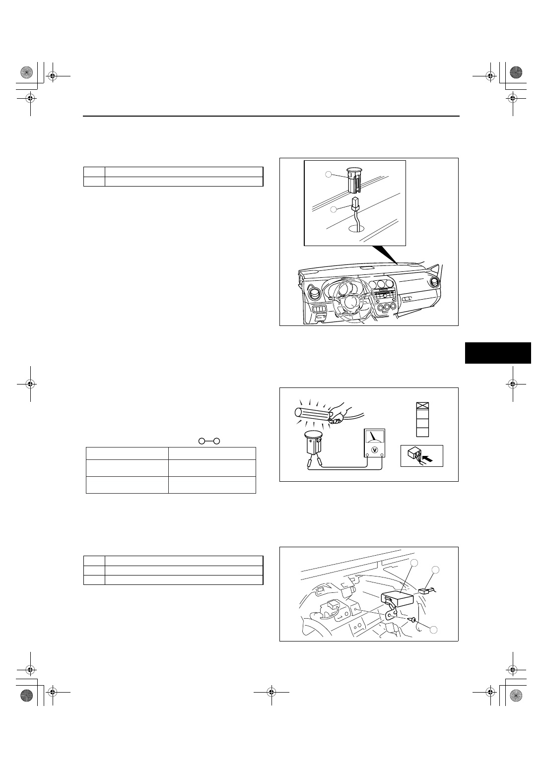
AUTO LIGHT SENSOR INSPECTION

id091800807600

Note

• Inspect the auto light sensor from the back side of the connector with the connector still connected.

1. Measure the voltage at auto light sensor terminal A and verify that the voltage is 5 V.
2. Shine a fluorescent light or expose the auto light sensor to natural sunlight.
3. Connect the positive (+) lead to terminal B and 

the negative (

−) lead to terminal C of the auto light 

sensor, and verify that the voltages are as shown 
in the table.

• If the voltage is not as specified, replace the 

auto light sensor.

End Of Sie

AUTO LIGHT CONTROL MODULE REMOVAL/INSTALLATION

id091800807300

1. Disconnect the negative battery cable.
2. Remove the meter hood. (See 09-17-10 METER HOOD REMOVAL/INSTALLATION.)
3. Remove the instrument cluster. (See 09-22-2 INSTRUMENT CLUSTER REMOVAL/INSTALLATION.)
4. Remove in the order indicated in the table.

5. Install in the reverse order of removal.

End Of Sie

1

Connector

2

Auto light sensor

1

2

acxuuw00001753

A

B

C

acxuuw00002401

Voltage (V)

Test condition

: Continuity 

Sensor subject to fluorescent 
light or natural sunlight

Sensor covered by a cloth

0.21

4.65

0.20 or less

acxuuw00002542

1

Screw

2

Connector

3

Auto light control module

3

1

2

acxuuw00001754

LIGHTING SYSTEMS 

09-18–20

AUTO LIGHT CONTROL MODULE INSPECTION

id091800807400

1. Measure the voltage at the auto light control module terminals as indicated below.
2. Disconnect the auto light control module connector before inspecting for continuity at terminals 1K, 2A, 2O and 

2P.

• If not as specified, inspect the parts listed under “Action.”

• If the parts and wiring harnesses are okay but the system still does not work properly, replace the auto light 

control module.

Terminal Voltage List (Reference)

Terminal

Signal

Connection

Test condition

Voltage (V)/

Continuity

Action

1A*

Power supply

DRL 15 A fuse

Constant

B+

• Inspect DRL 15 A 

fuse

• Inspect related 

harness

1D*

Headlight (LH) 
operation 
(high-beam)

Headlight (LH) 
(high-beam)

Light switch at 
headlight 
position

Dimmer switch at 
the high-beam 
position

B+

• Inspect headlight 

(LH)

• Inspect related 

harness

Dimmer switch at 
the low-beam 
position

1.0 or less

1G*

Headlight (LH) 
operation 
(high-beam)

Headlight (LH) 
(high-beam)

Light switch at 
headlight 
position

Dimmer switch at 
the high-beam 
position

1.0 or less

• Inspect headlight 

(LH)

• Inspect related 

harness

DRL mode

B+

1H*

Headlight (RH) 
operation 
(high-beam)

Headlight (RH) 
(high-beam)

Light switch at 
headlight 
position

Dimmer switch at 
the high-beam 
position

B+

• Inspect headlight 

(RH)

• Inspect related 

harness

Dimmer switch at 
the low-beam 
position

1.0 or less

1K*

Ground

GND

Constant: check for continuity to 
ground

Yes

Inspect GND

2A

Ground

GND

Constant: check for continuity to 
ground

Yes

Inspect GND

2B

Auto light 
sensor input

Auto light sensor

fluorescent light shined directly on the 
auto light sensor

0.21—4.65

• Inspect auto light 

sensor

• Inspect related 

harness

Blocking light to auto light sensor

0.20 or less

• Inspect auto light 

sensor

• Inspect related 

harness

2C

IG1

METER 10 A 
fuse

Ignition switch at ON

B+

• Inspect METER 10 A 

fuse

• Inspect related 

harness

Ignition switch at LOCK or ACC

1.0 or less

2B

*

2A

2C

2G

2H

2I

2K

2L

2M

2N

2O

2P

*

*

1A

1K

1D

AUTO LIGHT CONTROL MODULE 

HARNESS SIDE CONNECTOR

*

1G

*

*

*

1H

*

*

*

2J

acxuuw00001826

LIGHTING SYSTEMS 

09-18–21

09-18

*

: For vehicles with DRL only.

End Of Sie

2G

Power supply

ROOM 15 A 
fuse

Constant

B+

• Inspect ROOM 15 A 

fuse

• Inspect related 

harness

2H

Auto light 
sensor power 
supply

Auto light sensor Constant

5

• Inspect auto light 

sensor

• Inspect related 

harness

2I*

Front fog light 
relay on/off

Front fog light 
relay

Light switch at 
headlight 
position and 
dimmer switch at 
LO

Front fog light 
switch at ON

2.0 or less

• Inspect front fog light 

relay

• Inspect related 

harness

Front fog light 
switch at OFF

B+

2J*

Front fog light 
switch on/off

Front fog light 
switch

Light switch at 
headlight 
position and 
dimmer switch at 
LO

Front fog light 
switch at ON

1.0 or less

• Inspect light switch

• Inspect related 

harness

Front fog light 
switch at OFF

B+

2K*

High-beam on/
off

Light switch

Light switch at 
headlight 
position

Dimmer switch at 
HI

1.0 or less

• Inspect light switch

• Inspect related 

harness

Dimmer switch at 
LO

B+

2L

Light switch 
(Auto) signal

Light switch

Ignition switch at 
ON

Light switch at 
AUTO position

1.0 or less

• Inspect light switch

• Inspect related 

harness

Other

B+

2M

TNS relay 
operation/TNS 
switch on/off

TNS relay

Ignition switch at 
ON and light 
switch at AUTO 
position

Parking lights turn 
on (Sensor voltage 
is 0.3 V or less.)

1.0 or less

• Inspect TNS 15 A 

fuse

• Inspect TNS relay

• Inspect related 

harness

Parking lights turn 
off (Sensor voltage 
is 2.3 V or more.)

B+

Light switch

Ignition switch at 
ON

Light switch at TNS 
or headlight 
position

1.0 or less

• Inspect light switch

• Inspect related 

harness

Light switch at OFF 
position

B+

2N

Headlight relay 
operation/
headlight 
switch on/off

Headlight relay

Ignition switch at 
ON and light 
switch at AUTO 
position

Headlights (low-
beam) turn on
(Sensor voltage is 
0.3 V or less.)

1.0 or less

• Inspect headlight 

relay

• Inspect related 

harness

Headlights (low-
beam) turn off
(Sensor voltage is 
2.3 V or more.)

B+

Light switch

Light switch at headlight position

1.0 or less

• Inspect light switch

• Inspect related 

harness

Light switch at OFF or TNS position

B+

2O

Ground

GND

Constant: check for continuity to 
ground

Yes

Inspect GND

2P*

Parking brake 
lever 
depressed/ 
released

Parking brake 
switch

Parking brake lever depressed: check 
for continuity to ground

Yes

• Inspect parking 

brake switch

• Inspect related 

harness

Parking brake lever released: check 
for continuity to ground

No

Terminal

Signal

Connection

Test condition

Voltage (V)/

Continuity

Action

LIGHTING SYSTEMS 

09-18–22

AUTO LIGHT ILLUMINATION LEVEL SETTING

id091800803300

Caution

• If any of the following occurs, the sensitivity cannot be set properly. Therefore, resume from Step 

1.

• Each procedure and operation interval exceeds 5 s.

• Procedures are performed incorrectly.

Note

• Perform the procedure in a condition that allows verification of the headlight illumination because it is 

necessary to verify the setting condition according to the number of times headlights turn on.

1. Turn the ignition switch to the ON position with the light switch in the OFF position and pulled back (Flash-to-

pass ON).

2. Switch the light switch from the OFF to TNS position five times and return it to the OFF position.
3. Pull the light switch back once. (Flash-to-pass ON)
4. Turn the light switch to the TNS position.
5. Switch the light switch from the TNS to ON position five times and return it to the TNS position.
6. Turn the light switch to the ON position.
7. Switch the light switch from the ON to AUTO position five times and return it to the ON position.
8. Turn the light switch to the TNS position.

Note

• Switches to the sensitivity setting mode when the above operations are performed.

• The headlights turn on for the number of times according to the current setting conditions.

— Illumination (Two times): Standard sensitivity

— Illumination (Three times): Low sensitivity

9. Switch the sensitivity by pulling the light switch back (Flash-to pass ON).

10. Verify the number of times the headlights turn on and that the sensitivity is set properly.

• Illumination (Two times): Standard sensitivity

• Illumination (Three times): Low sensitivity

End Of Sie

WM: INTERIOR LIGHT

MAP LIGHT REMOVAL/INSTALLATION

id091800801200

1. Disconnect the negative battery cable.
2. Insert a scraper into the gap between the headliner and the map light.
3. Press the tab and remove the map light.

4. Disconnect the connector.
5. Remove the socket, then remove the map light 

bulb.

6. Install in the reverse order of removal.

End Of Sie

TAB

acxuuw00001759

MAP LIGHT

MAP 
LIGHT 
BULB

SOCKET

CONNECTOR

MAP LIGHT 
BULB

SOCKET

CONNECTOR

acxuuw00001760


Content   ..  419  420  421  422   ..