Mazda CX 7. Manual - part 380
GLASS/WINDOWS/MIRRORS
09-12–7
09-12
10. Remove the rear power window regulator through
the speaker installation hole.
11. Install in the reverse order of removal.
Caution
• Make sure the cable does not unspool
from the drum housing when installing.
End Of Sie
WM: WINDOW MOTOR
POWER WINDOW MOTOR REMOVAL/INSTALLATION
id091200803700
1. Fully lower the rear door glass.
2. Disconnect the negative battery cable.
3. Remove the following parts:
Front door
• Inner garnish (See.09-17-20 INNER GARNISH REMOVAL/INSTALLATION)
• Front door trim (See.09-17-20 FRONT DOOR TRIM REMOVAL/INSTALLATION)
Rear door
• Sail garnish (See.09-17-12 SAIL GARNISH REMOVAL/INSTALLATION)
• Rear door trim (See.09-17-23 REAR DOOR TRIM REMOVAL/INSTALLATION)
4. Remove the bolts.
5. Remove the power window motor from the power
window regulator.
6. Disconnect the power window motor connector.
7. Install in the reverse order of removal.
Note
• When installing the power window motor to
the power window regulator drum, the drum
housing tabs may detach from the door
module. If this happens, insert a hand
through the speaker installation hole to
engage the drum housing tabs, and install
the power window motor to the drum while
supporting the drum housing.
End Of Sie
POWER WINDOW MOTOR INSPECTION
id091200800800
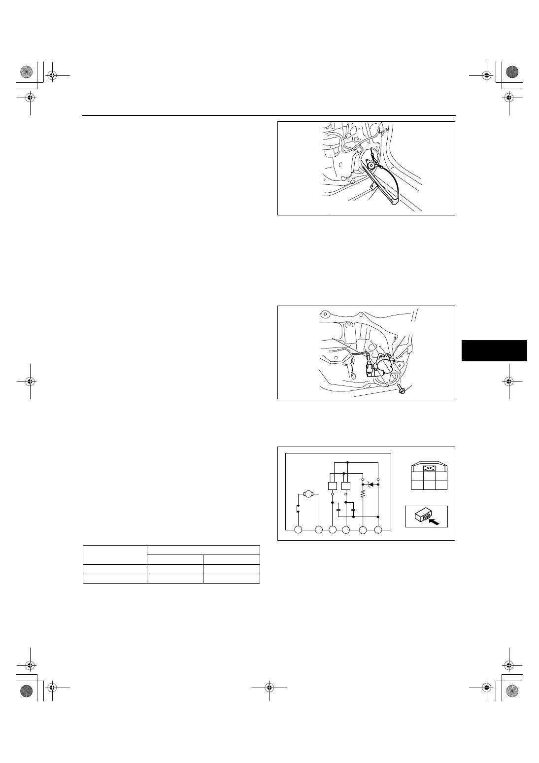
Front Side
1. Apply battery positive voltage and connect the
ground to power window motor terminals E and F,
and then inspect the power window motor
operation.
• If the power window motor does not operate
as indicated in the table, replace it.
Caution
• If the power window motor temperature is
high, the motor may not rotate due to the
motor internal bimetal function. Leave it
untouched for about 3 min to cool it
down, then reinspect.
2. Connect the battery positive voltage to power window motor terminal D and connect terminal C to ground.
3. Operate the power window motor and measure the voltage at terminals A and B.
• If there is any malfunction, replace the power window motor.
Voltage
• Pulse: max. 12 V/min. 0 V
REAR POWER WINDOW
REGULATOR
acxuuw00001471
POWER WINDOW
MOTOR
POWER WINDOW
MOTOR CONNECTOR
6.2—8.2 N·m
{64—83 kgf·cm,
55—72 in·lbf}
BOLT
acxuuw00001506
Operation
Terminal
F
E
Open
B+
Ground
Close
Ground
B+
F
A
C
E
B
D
F
M
E
B
A
D
C
acxuuw00001507