Mazda CX 7. Manual - part 363


  Index      Mazda     Mazda CX 7 - service repair manual 2007 year


Search            


Content   ..  361  362  363  364   ..


Mazda CX 7. Manual - part 363


SYMPTOM TROUBLESHOOTING [RADIO]

09-03E–3

09-03E

CONFIRMATION STEP 2: ANTENNA SYSTEM SYMPTOM (EXAMPLE)[RADIO]

id0903e3804100

End Of Sie

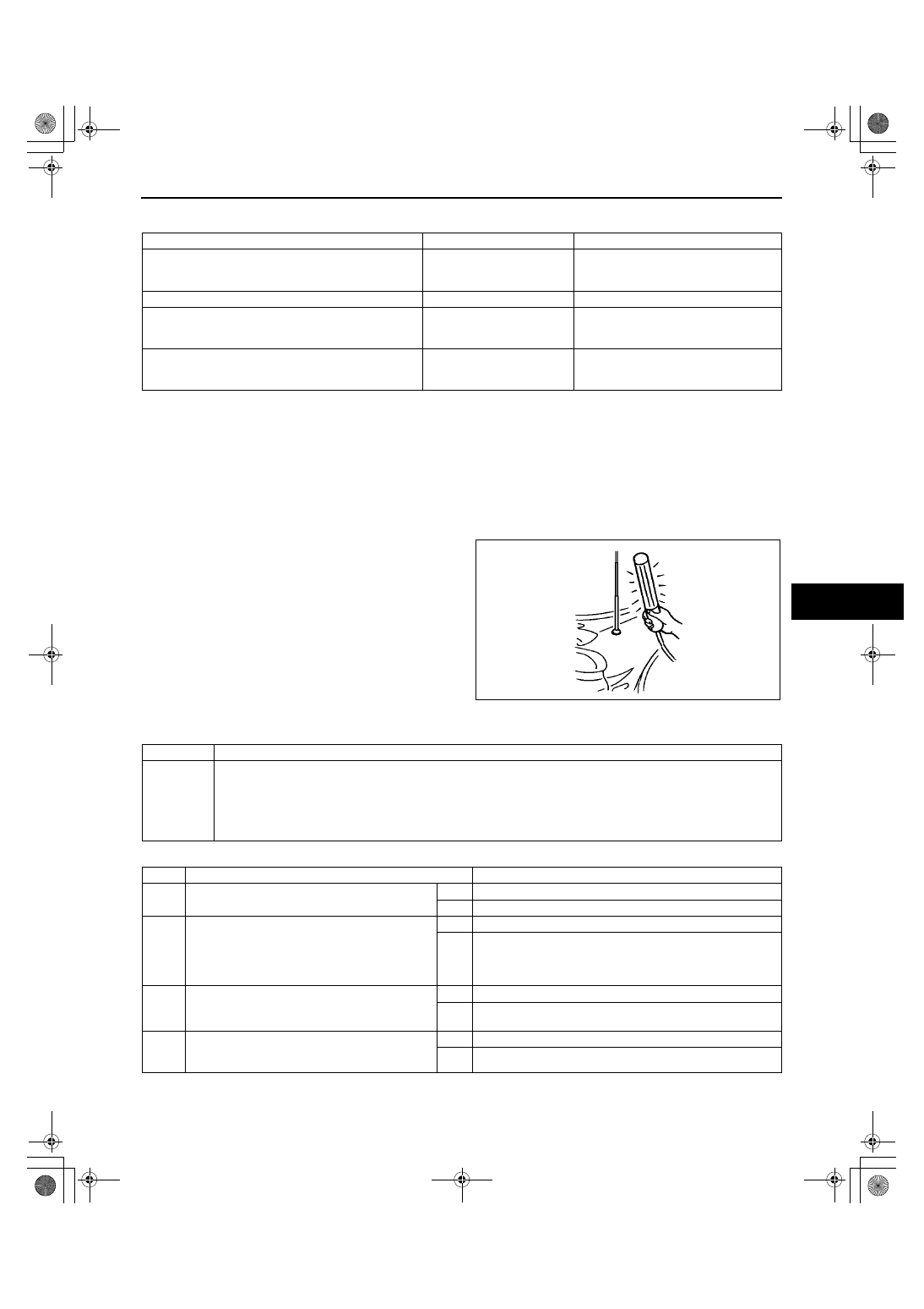
CONFIRMATION STEP 3: ANTENNA SYSTEM SIMPLE INSPECTION[RADIO]

id0903e3804200

• Because the antenna system is equipped with a capacitor, the continuity cannot be checked. Therefore 

proceed with the following simple inspection.

1. Turn the AM radio on.
2. Tune to the frequency that there is no broadcast and you will hear a buzzing sound.
3. Turn a fluorescent light on and shake it around the antenna rod (around 10—20 mm)

Note

• Use a fluorescent light type for the 

inspection. Accurate diagnostic cannot be 
done with a different type of light.

4. If a whirring sound from the speaker 

synchronized to the work light movement is 
confirmed, the antenna system is normal.

End Of Sie

NO.1 NO RADIO RECEPTION (AM/FM)/NO OR LOW VOLUME[RADIO]

id0903e3804300

Diagnostic procedure

Possible cause

AM reception condition

FM reception condition

• Antenna feeder axis, open circuit

• Antenna feeder plug not attached

NG: No reception

YES: Reception possible.
(Sensitivity decreases, but reception is 
possible under strong electric field.)

• Antenna feeder axis (+) to ground (-), open circuit NG: No reception

NG: No reception

• Antenna feeder and antenna, poor ground

YES: Reception possible
(Noise may occur)

YES: Reception possible
(Sensitivity decreases, but reception is 
possible under strong electric field.)

• Antenna feeder, jack and plug poor connection

NG: No reception
(Depending on connection 
conditions)

YES: Reception possible
(Depending on connection conditions)

acxuuw00000946

1

No radio reception (AM/FM)/no or low volume/Possible DTC: 09:Er20, 09:Er22

POSSIBLE 
CAUSE

• Jamming from aftermarket electronic equipment (two-way radio, navigation system, mobile phone, etc.)

• Audio unit malfunction

• Antenna plug poor connection

• Antenna feeder malfunction

• Electronic jamming from outside, or inferior condition of broadcasting station radio wave

• Antenna rod is not installed

STEP

INSPECTION

ACTION

1

• Turn the audio unit ON.

• Is the LCD indicated correctly?

Yes

Go to the Step 3.

No

Go to the next step.

2

• Measure voltage at B+ and ACC terminals.

• Is voltage okay?

Specification

With ignition switch ON: 11.5 V or more
At idling: 12.5 V or more

Yes

Go to the next step.

No

Follow diagnostic procedure for symptom No. 2 (Entire 
audio system).

3

• Set volume to 10 to 15.

• Is buzzing sound or voice confirmed?

Yes

Go to the next step.

No

Follow diagnostic procedure for symptom No. 3 (Entire 
audio system) or No. 4 (Entire audio system).

4

• Tune to local broadcasting station and check 

reception condition.

• Is reception okay?

Yes

Go to the next step.

No

Go to the Step 6.

1871-1U-06B(09-03E).fm  3 ページ  2006年3月16日 木曜日 午後4時10分

SYMPTOM TROUBLESHOOTING [RADIO]

09-03E–4

End Of Sie

5

• Push PRESET buttons and check preset 

conditions.

• Has preset been stored?

Yes

The system is normal.

No

Preset broadcasting stations.

6

• Is aftermarket electronic equipment (two-way 

radio, navigation system, mobile phone, etc.) 
installed?

Note

• TV antenna located closely to audio 

antenna can be cause of noise. Relocate 
TV antenna.

Yes

Go to the next step.

No

Go to the Step 8.

7

• Remove aftermarket electronic equipment.

• Turn audio unit ON and check reception 

condition.

• Is reception improved?

Yes

The system is normal.
(Explain to customers that aftermarket electronic equipment 
is cause of noise)

No

Go to the next step.

8

• Refer to confirmation step 3, and inspect 

antenna system.

• Is a whirring sound present?

Yes

Replace audio unit.

No

Go to the next step.

9

• Inspect antenna plug connection condition.

• Is connection okay?

Yes

Go to the next step.

No

Insert antenna plug securely.

10

• Turn ignition switch to LOCK position.

• Measure continuity between antenna feeder 

axis and ground.

• Is there any continuity?

Yes

Replace antenna feeder.

No

Go to the next step.

11

• Compare reception with other audio unit on 

same model (model/unit) under same 
problem conditions.

• Is reception equivalent between customer’s 

unit and compared unit?

Note

• Due to following differences, you may feel 

difference in reception efficiency.

(Vehicle side factor)

— Antenna installation location, height, 

feeder wiring routing, optional electrical 
equipment

(Audio unit factor)

— Volume concern type: It decreases 

change of volume when signals 
become weak. (Noise is conspicuous)

— Noise decrease type: It decreases 

volume when signals become weak, so 
that noise is not conspicuous.

Yes

The system is normal.
(It is caused by electronic jamming from outside, or inferior 
broadcasting station signal condition.)

No

Replace audio unit.

STEP

INSPECTION

ACTION

1871-1U-06B(09-03E).fm  4 ページ  2006年3月16日 木曜日 午後4時10分

SYMPTOM TROUBLESHOOTING [RADIO]

09-03E–5

09-03E

NO.2 NOISE FROM RADIO (AM ONLY)[RADIO]

id0903e3804400

Diagnostic procedure

2

Noise from radio (AM only)/Possible DTC: 09:Er22

POSSIBLE 
CAUSE

• Antenna rod not installed

• Jamming from aftermarket electronic equipment (two-way radio, navigation system, mobile phone, etc.)

• Noise from electrical system on vehicle (e.g. fuel pump)

• Battery malfunction

• Charging system malfunction

• Audio unit malfunction

• Antenna plug poor connection

• Antenna feeder malfunction

• Electronic jamming from outside, or inferior condition of broadcasting station radio wave

• Antenna installation loosened

STEP

INSPECTION

ACTION

1

• Tune to local broadcasting station and check 

reception condition.

• Is reception okay?

Yes

Tune to correct frequency of broadcasting station.
If not preset, preset it.

No

Go to the next step.

2

• Inspect antenna rod condition.

• Is antenna rod installed?

Yes

Go to the next step.

No

Advise customer to install antenna rod when radio is used.

3

• Is aftermarket electronic equipment (two-way 

radio, navigation system, mobile phone, etc.) 
installed?

Note

• TV antenna located closely to audio 

antenna can be cause of noise. Relocate 
TV antenna.

Yes

Go to the next step.

No

Go to the Step 5.

4

• Remove aftermarket electronic equipment.

• Turn audio unit ON and check reception 

condition.

• Is reception improved?

Yes

The system is normal. (Explain to customers that 
aftermarket electronic equipment is cause of noise)

No

Go to the next step.

5

• Measure battery voltage.

• Is battery voltage okay?

Standard

With ignition switch ON: 11.5 V or more
At idling: 12.5 V or more

Note

• Inspect that battery cables are connected 

to terminals securely.

Yes

Go to the next step.

No

Charge battery. Inspect charging system, and repair or 
replace if necessary.

6

• Is noise occurring only when vehicle 

electrical system (e.g. fuel pump) operates?

Note

• Identify subject electrical component by 

disconnecting fuse, turning switch ON & 
OFF, or disconnecting & connecting 
connector.

• It will be easy when simulation function on 

M-MDS is used.

Yes

Go to the next step.

No

Go to the Step 8.

7

• Inspect power supply, ground condition, and 

noise prevention capacitor for electrical 
component.

• Is noise present after inspection?

Note

• Inspect following:

— Power supply to electrical component 

for voltage drop (compare with battery 
voltage)

— Resistance between ground of 

electrical component and body. 
(Should be close to 0 ohm)

— Installation condition of noise 

prevention capacitor for fuel pump etc.

Yes

Go to the next step.

No

Troubleshooting completed.

Note

• The audio unit supplies 12 V battery power to the 

antenna amplifier for the AM radio reception in the 
radio mode. The audio unit cannot receive the AM 
signals without the 12 V battery power to the antenna 
amplifier. If the AM signals become strong, the audio 
unit may receive the signal with noises.

1871-1U-06B(09-03E).fm  5 ページ  2006年3月16日 木曜日 午後4時10分

SYMPTOM TROUBLESHOOTING [RADIO]

09-03E–6

End Of Sie

NO.3 NOISE FROM RADIO (FM ONLY)[RADIO]

id0903e3804500

Diagnostic procedure

8

• Inspect antenna plug connection condition.

• Is connection okay?

Yes

Go to the next step.

No

Insert antenna plug securely.

9

• Turn ignition switch to LOCK position.

• Measure continuity between antenna feeder 

axis and ground.

• Is there any continuity?

Yes

Replace antenna feeder.

No

Go to the next step.

10

Compare reception with other audio unit on 
same model (model/unit) under same problem 
conditions.

• Is reception equivalent between customer’s 

unit and compared unit?

Note

• Due to following differences, you may 

detect a difference in reception efficiency.

(Vehicle side factor)

— Antenna installation location, height, 

feeder wiring routing, optional electrical 
equipment

(Audio unit factor)

— Volume concern type: It decreases 

change of volume when signals 
become weak. (Noise is conspicuous)

— Noise decrease type: It decreases 

volume when signals become weak, so 
that noise is not conspicuous.

Yes

The system is normal (It is caused by electronic jamming 
from outside, or inferior broadcasting station signal 
condition).

No

Go to the next step.

11

• Retighten ground fixation for antenna 

installation part and antenna amplifier. 
Retighten antenna rod.

• Is noise present, after retightening?

Yes

Replace audio unit.

No

Troubleshooting completed.

STEP

INSPECTION

ACTION

3

Noise from radio (FM only)/Possible DTC: 09:Er22

POSSIBLE 
CAUSE

• Antenna rod not installed

• Jamming from aftermarket electronic equipment (two-way radio, navigation system, mobile phone, etc.)

• Noise from electrical system on vehicle (e.g. fuel pump)

• Battery malfunction

• Charging system malfunction

• Audio unit malfunction

• Antenna plug poor connection

• Antenna feeder malfunction

• Electronic jamming from outside, or inferior condition of broadcasting station radio wave

• Antenna installation loosened

Note

• FM broadcast has feature “sound quality is good” and “resistant to noise”, but FM broadcast has particular 

noises. Though audio unit is designed to reduce noise, there are times noise occurs due to conditions.

STEP

INSPECTION

ACTION

1

• Tune to local broadcasting station and check 

reception condition.

• Is reception okay?

Yes

Tune to correct frequency of broadcasting station.
If not preset, preset it.

No

Go to the next step.

2

• Inspect antenna rod condition.

• Is antenna rod installed?

Yes

Go to the next step.

No

Advise customer to install antenna rod when radio is used.

3

• Is aftermarket electronic equipment (two-way 

radio, navigation system, mobile phone, etc.) 
installed?

Yes

Go to the next step.

No

Go to the Step 5.

4

• Remove aftermarket electronic equipment.

• Turn audio unit ON and check reception 

condition.

• Is reception improved?

Yes

The system is normal. (Explain to customers that 
aftermarket electronic equipment is cause of noise)

No

Go to the next step.

1871-1U-06B(09-03E).fm  6 ページ  2006年3月16日 木曜日 午後4時10分


Content   ..  361  362  363  364   ..