Mazda CX 7. Manual - part 338
ON-BOARD DIAGNOSTIC [MULTIPLEX COMMUNICATION SYSTEM]
09-02D–9
09-02D
2007 Mazda CX-7 Workshop Manual (1871–1U–06B)
Revised 12/2006 (Ref. No. R215/06)
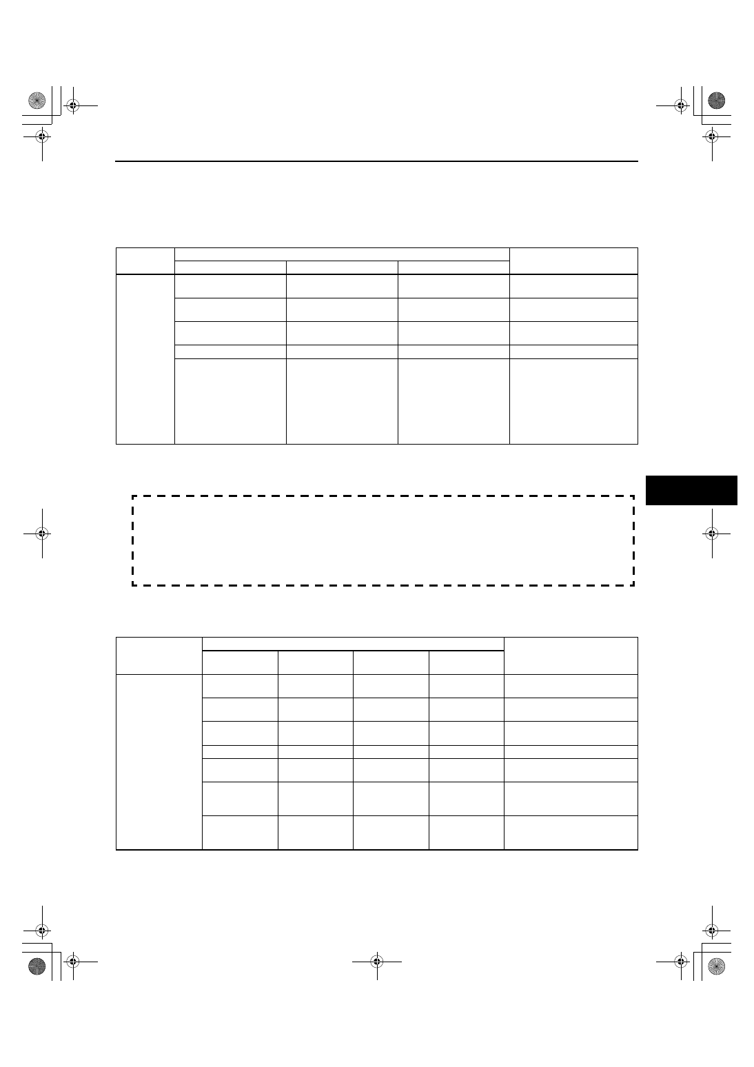
TCM
1. Inspect the display of DTC U0100, U0121, U0140 and/or U0415 using the M-MDS. (See 09-02D-7 DTC
TABLE[MULTIPLEX COMMUNICATION SYSTEM].)
2. Referring to the following table, determine the malfunctioning part of the CAN system.
×: Normal
— : Communication error
DSC HU/CM
1. Inspect the display of DTC U0100, U0101, U0114, U0140, U1900 and/or U2023 using the M-MDS. (See 09-
02D-7 DTC TABLE[MULTIPLEX COMMUNICATION SYSTEM].)
Caution
• DTC U2023 may not be cleared during engine starting even if DTC clearing is done using the M-
MDS. When clearing DTC U2023, execute with the ignition switch in the ON position (Engine off).
Note
• You may want to check which unit is malfunctioning according to Freeze Frame Data. "Electrical" > "IC
Service Function" > "Freeze Frame Data".This function is supported on IDS, not PDS.
2. Referring to the following table, determine the malfunctioning part of the CAN system.
×: Normal
— : Communication error
Module
Communication status
Malfunction location
PCM
DSC HU/CM
Instrument cluster
TCM
— — —
• Wiring harness B
• TCM
—
×
×
• Wiring harness A
• PCM
×
—
×
• Wiring harness D
• DSC HU/CM
×
— —
• Wiring harness C
×
×
—
• Wiring harness E
• BCM
• Wiring harness F
• Wiring harness H
• Wiring harness J
• Wiring harness K
• Wiring harness M
• Instrument cluster
Module
Communication status
Malfunction location
PCM
TCM
AWD control
module
BCM
DSC HU/CM
— — — —
• Wiring harness D
• DSC HU/CM
—
×
×
×
• Wiring harness A
• PCM
×
—
×
×
• Wiring harness B
• TCM
— —
×
×
• Wiring harness C
×
×
—
×
• Wiring harness G
• AWD control module
×
×
— —
• Wiring harness E
• BCM
• Wiring harness F
×
×
×
—
• Wiring harness H
• Wiring harness J
• BCM