Mazda CX 7. Manual - part 319
AIR BAG SYSTEM
08-10–13
08-10
SIDE AIR BAG SENSOR NO. 1 REMOVAL/INSTALLATION
id081000800600
Warning
• Handling the side air bag sensor improperly can accidentally operate (deploy) the air bag module,
which may seriously injure you. Read the air bag system service warnings and cautions before
handling the side air bag sensor. (See 08-10-3 AIR BAG SYSTEM SERVICE WARNINGS.) (See 08-
10-5 AIR BAG SYSTEM SERVICE CAUTIONS.)
1. Turn the ignition switch to the LOCK position.
2. Disconnect the negative battery cable and wait for 1 min or more.
3. Remove the following parts:
(1) Front scuff plate inner (See 09-17-19 FRONT SCUFF PLATE REMOVAL/INSTALLATION.)
(2) Rear scuff plate inner (See 09-17-19 REAR SCUFF PLATE REMOVAL/INSTALLATION.)
(3) B-pillar lower trim (See 09-17-16 B-PILLAR LOWER TRIM REMOVAL/INSTALLATION.)
4. Remove in the order indicated in the table.
5. Install in the reverse order of removal.
6. Turn the ignition switch to the ON position and
hold for 10 s or more.
7. Verify that the air bag system warning light
illuminates for approx. 6 s and goes out.
• If the air bag system warning light does not
operate normally, refer to the on-board
diagnostic system (air bag system) and perform inspection of the system.
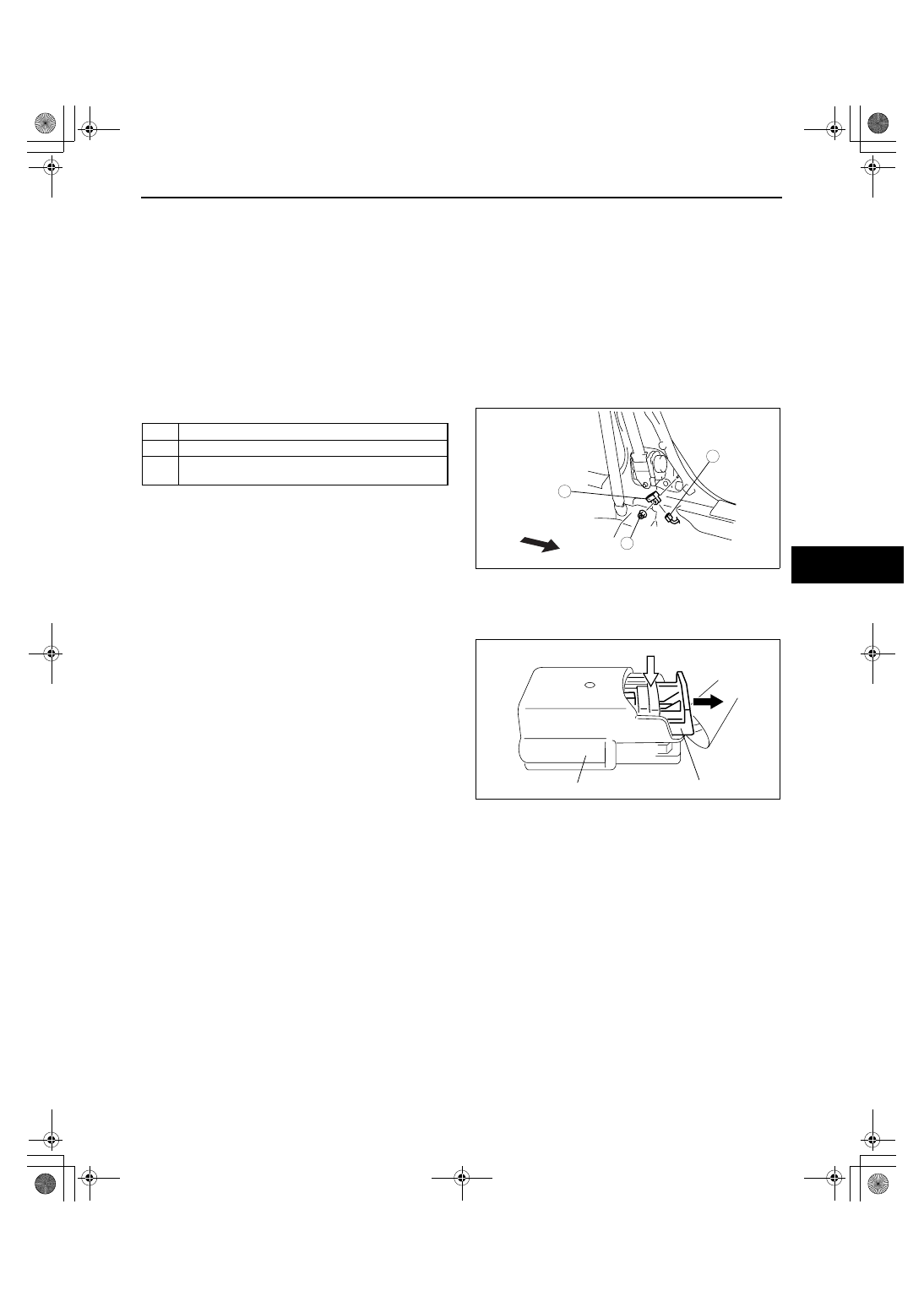
Connector Removal Note
1. Disconnect the connector from the side air bag
sensor No.1 by pressing the connector tab and
pulling out the lock lever in the direction of the
arrow.
End Of Sie
1
Nut
2
Side air bag sensor No. 1
3
Connector
(See 08-10-13 Connector Removal Note.)
3
1
2
8.8—12.8 N·m
{89.8—130.5 kgf·cm,
77.8—113.2 in·lbf}
FRONT
acxuuw00000644
TAB
CONNECTOR
LOCK LEVER
acxuuw00000643
1871-1U-06B(08-10).fm 13 ページ 2006年3月15日 水曜日 午前11時36分