Mazda CX 7. Manual - part 293


  Index      Mazda     Mazda CX 7 - service repair manual 2007 year


Search            


Content   ..  291  292  293  294   ..


Mazda CX 7. Manual - part 293


BASIC SYSTEM 

07-11–17

07-11

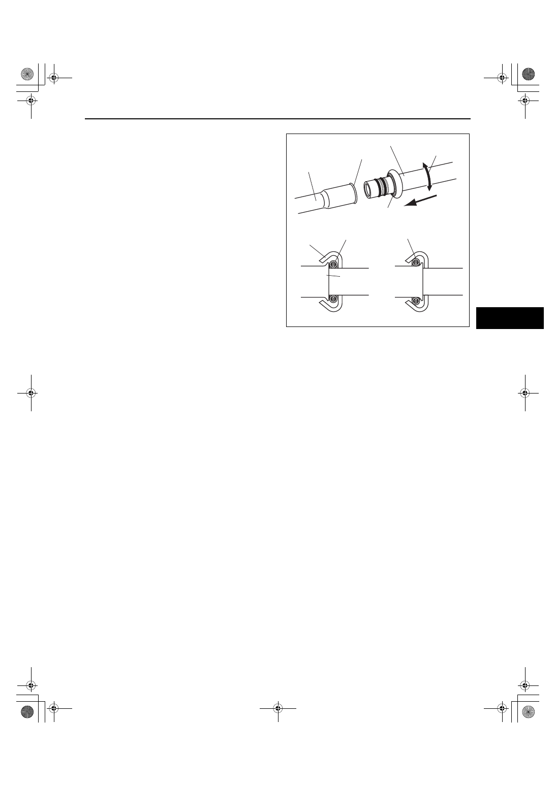
Spring-lock coupling type

1. Connect the male pipe or hose by pushing it while 

slightly twisting it onto female pipe until the garter 
spring at the male pipe or hose is over the flared 
end of female pipe.

Note

• When the male pipe or hose is replaced, the 

indicator ring comes out after connecting to 
indicate that it is locked.

End Of Sie

WM: CONDENSER

CONDENSER REMOVAL/INSTALLATION

id071100801200

1. Disconnect the negative battery cable.
2. Discharge the refrigerant from the system. (See 07-10-6 REFRIGERANT RECOVERY.) (See 07-10-2 

REFRIGERANT CHARGING.)

3. Remove the air cleaner. (See 01-13-5 INTAKE AIR SYSTEM REMOVAL/INSTALLATION[L3 WITH TC].)
4. Remove the splash shield.
5. Drain the engine coolant. (See 01-12-5 ENGINE COOLANT REPLACEMENT[L3 WITH TC].)
6. Remove the following parts:

(1) Charge air cooler duct, air cleaner and fresh air duct component (See 01-13-5 INTAKE AIR SYSTEM 

REMOVAL/INSTALLATION[L3 WITH TC].)

(2) Coolant reserve tank (See 01-12-7 COOLANT RESERVE TANK REMOVAL/INSTALLATION[L3 WITH TC].)
(3) Dipstick pipe (See 01-11-6 OIL PAN REMOVAL/INSTALLATION[L3 WITH TC].)
(4) Cooling fan component (See 01-12-12 FAN MOTOR REMOVAL/INSTALLATION[L3 WITH TC].)

7. Remove the radiator. (See 01-12-8 RADIATOR REMOVAL/INSTALLATION[L3 WITH TC].)

Caution

• If moisture or foreign material enters the refrigeration cycle, cooling ability will be lowered and 

abnormal noise will occur. Always immediately plug all open fittings after removing any 
refrigeration cycle parts to keep moisture or foreign material out of the cycle.

8. Remove in the order indicated in the table. Do not allow compressor oil to spill. 

FLARED END

FEMALE PIPE

MALE PIPE OR HOSE

GARTER SPRING

CAGE
SECTION

GARTER SPRING

SPRING IS OVER
THE FLARED END

FLARED
END

WRONG

RIGHT

SLIGHTLY TWISTING

PUSHING

acxuuw00000787

1871-1U-06B(07-11).fm  17 ページ  2006年3月15日 水曜日 午前11時30分

BASIC SYSTEM 

07-11–18

9. Install in the reverse order of removal.

10. Perform the refrigerant system performance test. (See 07-10-6 REFRIGERANT SYSTEM PERFORMANCE 

TEST.)

Condenser Installation Note

1. After replacing the condenser, add compressor oil to the refrigeration cycle.

Supplemental oil amount (approx. quantity)

20 ml {20 cc, 0.7 fl oz}

End Of Sie

CONDENSER INSPECTION

id071100801300

1. Inspect for cracks, damage, and oil leakage.

• If any are found, replace the condenser.

2. Inspect for fins clogged by dust.

• If any are clogged, remove the dust from the fins.

3. Inspect for bent fins.

• If any are bent, use a flathead screwdriver to straighten them.

End Of Sie

WM: RECEIVER/DRIER

1

R

R

6.8—9.8 N·m 
{69.4—99.9 kgf·cm, 
61.6—88.7 in·lbf}

4

3

2

acxuuw00002305

1

Nut

2

Cooler hose (HI)
(See 07-11-15 REFRIGERANT LINES REMOVAL/
INSTALLATION.)

3

Cooler pipe
(See 07-11-15 REFRIGERANT LINES REMOVAL/
INSTALLATION.)

4

Condenser
(See 07-11-17 CONDENSER REMOVAL/
INSTALLATION.)

1871-1U-06B(07-11).fm  18 ページ  2006年3月15日 水曜日 午前11時30分

BASIC SYSTEM 

07-11–19

07-11

RECEIVER/DRIER REMOVAL/INSTALLATION

id071100801400

1. Disconnect the negative battery cable.
2. Discharge the refrigerant from the system. (See 07-10-6 REFRIGERANT RECOVERY.) (See 07-10-2 

REFRIGERANT CHARGING.)

3. Remove the front bumper. (See 09-10-2 FRONT BUMPER REMOVAL/INSTALLATION.)
4. Remove the oil cooler. (See 01-11-6 OIL COOLER REMOVAL/INSTALLATION[L3 WITH TC].)

Caution

• If moisture or foreign material enters the refrigeration cycle, cooling ability will be lowered and 

abnormal noise will occur. Always immediately plug all open fittings after removing any 
refrigeration cycle parts to keep moisture or foreign material out of the cycle.

5. Remove the receiver/drier. Do not allow compressor oil to spill. (See 07-11-19 Receiver/Drier Removal Note.)

6. Install in the reverse order of removal. (See 07-11-20 Receiver/Drier Installation Note.)
7. Perform the refrigerant system performance test. (See 07-10-6 REFRIGERANT SYSTEM PERFORMANCE 

TEST.)

Receiver/Drier Removal Note

1. Disconnect the block joint type pipes by grasping 

female side of the block with hand and holding 
firmly, then tighten the connection bolt.

6.85—9.80 N·m 
{70.0—99.9 kgf·cm, 
60.8—86.7 in·lbf}

6.85—9.80 N·m 
{70.0—99.9 kgf·cm, 
60.8—86.7 in·lbf}

RECEIVER/DRIER

R

acxuuw00002231

MALE SIDE BLOCK

FEMALE SIDE BLOCK

acxuuw00000789

1871-1U-06B(07-11).fm  19 ページ  2006年3月15日 水曜日 午前11時30分

BASIC SYSTEM 

07-11–20

Receiver/Drier Installation Note

1. Tighten the bolt of joint by hand.
2. Tighten the joint to the specified torque.
3. Connect the block joint type pipe by grasping the 

female side of the block with hand holding firmly, 
then tighten the connection bolt.

End Of Sie

WM: EVAPORATOR

EVAPORATOR INSPECTION

id071100801500

1. Remove the A/C unit. (See 07-11-2 A/C UNIT REMOVAL/INSTALLATION.)
2. Remove the evaporator from the A/C unit.
3. Inspect for cracks, damage, and oil leakage.

• If any problems are found, replace the evaporator.

4. Inspect for bent fins.

• If any are bent, use a flathead screwdriver to straighten them.

End Of Sie

WM: HEATER CORE

HEATER CORE INSPECTION

id071100801600

1. Remove the A/C unit. (See 07-11-2 A/C UNIT REMOVAL/INSTALLATION.)
2. Remove the heater core from the A/C unit.
3. Inspect for cracks, damage, and coolant leakage.

• If any problems are found, replace the heater core.

4. Inspect for bent fins.

• If any are bent, use a flathead screwdriver to straighten them.

5. Verify that the heater core inlet and outlet pipe are not distorted or damaged.

• Repair with pliers if necessary.

End Of Sie

MALE SIDE BLOCK

FEMALE SIDE BLOCK

acxuuw00000790

1871-1U-06B(07-11).fm  20 ページ  2006年3月15日 水曜日 午前11時30分


Content   ..  291  292  293  294   ..