Mazda CX 7. Manual - part 285


  Index      Mazda     Mazda CX 7 - service repair manual 2007 year


Search            


Content   ..  283  284  285  286   ..


Mazda CX 7. Manual - part 285


SYMPTOM TROUBLESHOOTING 

07-03–13

07-03

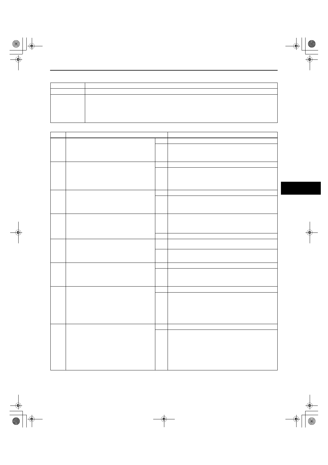
NO.7 AIR FROM VENTS NOT COLD ENOUGH

id070300801000

Diagnostic procedure

7

Air from vents not cold enough.

DESCRIPTION

• Magnetic clutch operates but A/C system malfunctions.

POSSIBLE 

CAUSE

• Drive belt malfunction

• A/C unit or condenser malfunction

• Receiver/drier or expansion valve malfunction (valve closes too much)

• Malfunction in refrigerant lines

• A/C compressor system malfunction, insufficient compressor oil

• Over filling of compressor oil, malfunction in expansion valve or A/C unit air mix link system

STEP

INSPECTION

ACTION

1

INSPECT DRIVE BELT

• Inspect the drive belt.

 (See 01-10-3 DRIVE BELT INSPECTION[L3 
WITH TC].)

• Is it normal?

Yes

Go to the next step.

No

Adjust or replace the drive belt, then go to Step 20.
 (See 01-10-3 DRIVE BELT REMOVAL/INSTALLATION[L3 
WITH TC].)

2

INSPECT REFRIGERANT SYSTEM 
PERFORMANCE

• Perform refrigerant system performance test.

 (See 07-10-6 REFRIGERANT SYSTEM 
PERFORMANCE TEST.)

• Is the operation normal?

Yes

Operation is normal. (Recheck malfunction symptoms.)

No

Go to the next step.

3

INSPECT TO SEE WHETHER MALFUNCTION 
IS IN A/C UNIT INTAKE AND CONDENSER 
OR ELSEWHERE

• Are the refrigerant high-pressure and low-

pressure values both high?

Yes

Go to the next step.

No

Go to Step 6.

4

INSPECT A/C UNIT INTAKE

• Is the A/C unit intake clogged?

Yes

Remove obstruction, then go to Step 20. (If air does not 
reach the evaporator in the A/C unit, heat exchange does 
not occur and refrigerant pressure becomes high.
Therefore, removal of obstruction is necessary.)

No

Go to the next step.

5

INSPECT CONDENSER

• Inspect the condenser.

 (See 07-11-18 CONDENSER 
INSPECTION.)

• Is it normal?

Yes

Adjust refrigerant to the specified amount, then go to Step 
20. (Excessive amount of refrigerant.)

No

Replace the condenser, or repair and clean the condenser 
fins, then go to Step 20.

6

INSPECT TO SEE WHETHER MALFUNCTION 
IS IN EXPANSION VALVE, RECEIVER/DRIER 
AND REFRIGERANT LINES OR ELSEWHERE

• Are the refrigerant high-pressure and low-

pressure values low?

Yes

Go to the next step.

No

Go to Step 14.

7

INSPECT TO SEE WHETHER MALFUNCTION 
IS IN EXPANSION VALVE AND RECEIVER/
DRIER OR ELSEWHERE

• Immediately after the A/C compressor 

operates, does the refrigerant high-pressure 
value momentarily rise to correct value, then 
fall and stay below it? (Is there negative 
pressure on low-pressure side?)

Yes

Go to the next step.

No

Go to Step 10.

8

INSPECT TO SEE WHETHER MALFUNCTION 
IS IN EXPANSION VALVE OR RECEIVER/
DRIER

• Turn the A/C switch off and let the air 

conditioner stop for 10 min.

• Start the engine.

• Turn the both A/C switch and airflow volume 

control dial on.

• Does the malfunction occur after the A/C 

compressor turns on?

Yes

Go to the next step.

No

Replace the condenser and vacuum the refrigerant line 
more than 30 min by the vacuum pump, add refrigerant to 
the specified level, then go to Step 20. (Since water has 
intermixed in the receiver/drier and it is saturated, 
replacement is necessary.)

1871-1U-06B(07-03).fm  13 ページ  2006年3月15日 水曜日 午前11時28分

SYMPTOM TROUBLESHOOTING 

07-03–14

9

VERIFY THAT EXPANSION VALVE HEAT-
SENSING TUBE WITHIN A/C UNIT IS 
POSITIONED SECURELY AND CORRECTLY

• Is the expansion valve heat-sensing tube in 

the A/C unit securely installed in the proper 
position?

Yes

Replace the expansion valve, then go to Step 20. (Since the 
valve closes too much, replacement is necessary.)

No

Install the heat-sensing tube securely in the proper position, 
then go to Step 20.

10

INSPECT REFRIGERANT LINE

• Inspect the refrigerant lines.

— Is the piping free of damage and cracks?

— Are the piping connections free of oil 

grime? (Visual inspection)

— Are the piping connections free of gas 

leakage?

— Are the piping installation points on the 

condenser free of gas leakage?

— Are the piping installation points on the 

receiver/drier free of gas leakage?

— Are the piping installation points on the A/

C compressor free of gas leakage?

— Are the piping installation points on the A/

C unit free of gas leakage?

— Perform gas leakage inspection using a 

gas leak tester.

• Are the above items normal?

Yes

Go to the next step.

No

If the piping or A/C component (s) are damaged or cracked, 
replace them.
Then go to Step 20.
If there is no damage, go to Step 13.

11

INSPECT EVAPORATOR PIPING 
CONNECTION IN A/C UNIT FOR GAS 
LEAKAGE

• Are piping the connections for the evaporator 

in the A/C unit free of gas leakage?

Yes

If the vane makes a noise, add 10 ml {10 cc, 0.34 fl oz} of 
compressor oil to the A/C compressor. Verify that the noise 
is no longer heard.
Adjust refrigerant to the specified amount, then go to Step 
20.

No

If the piping is damaged or cracked, replace it.
Then go to Step 20.
If there is no damage, go to the next step.

12

INSPECT EVAPORATOR PIPING 
CONNECTION IN A/C UNIT FOR LOOSE

• Are the piping connections for the evaporator 

in the A/C unit loose?

Yes

Tighten the connections to the specified torque, adjust both 
compressor oil and refrigerant to the specified amount, then 
go to Step 20.

No

If the vane makes a noise, add 10 ml {10 cc, 0.34 fl oz} of 
compressor oil to the A/C compressor. Verify that the noise 
is no longer heard.
Replace the O-ring on piping, adjust refrigerant to the 
specified amount, then go to Step 20.

13

INSPECT PIPING CONNECTION FOR LOOSE

• Are the piping connections loose?

Yes

Tighten the connections to the specified torque, adjust both 
compressor oil and refrigerant to the specified amount, then 
go to Step 20.

No

If the vane makes a noise, add 10 ml {10 cc, 0.34 fl oz} of 
compressor oil to the A/C compressor. Verify that the noise 
is no longer heard.
Replace O-ring on piping, adjust refrigerant to specified 
amount, then go to Step 20.

14

INSPECT TO SEE WHETHER MALFUNCTION 
IS IN EXPANSION VALVE, AIR MIX 
ACTUATOR AND COMPRESSOR OIL OR 
ELSEWHERE

• Does the refrigerant high-pressure value 

hardly increase?

Yes

Go to the next step. (Pressure hardly increases.)

No

Go to Step 17.

15

INSPECT TO SEE WHETHER MALFUNCTION 
IS IN COMPRESSOR OIL AMOUNT AND A/C 
COMPRESSOR OR ELSEWHERE

• When the engine is racing, does the high-

pressure value increase?

Yes

Return to Step 3.

No

Go to the next step.

16

INSPECT TO SEE WHETHER MALFUNCTION 
IS IN COMPRESSOR OIL AMOUNT OR A/C 
COMPRESSOR

• After compressor oil is replenished each 10 

ml {10 cc, 0.34 fl oz}, does high-pressure 
value increase?

Yes

Troubleshooting completed. (Explain to customer that cause 
was insufficient compressor oil.)

No

Replace the A/C compressor, then go to Step 20. (Cause is 
defective A/C compressor.)

STEP

INSPECTION

ACTION

1871-1U-06B(07-03).fm  14 ページ  2006年3月15日 水曜日 午前11時28分

SYMPTOM TROUBLESHOOTING 

07-03–15

07-03

2007 Mazda CX-7 Workshop Manual (1871–1U–06B)

End Of Sie

NO.8 NO COOL AIR

id070300801100

• When performing an asterisked (*) troubleshooting inspection, shake the wiring harness and connectors while 

performing the inspection to discover whether poor contact points are the cause of any intermittent 
malfunctions. If there is a problem, check to make sure connectors, terminals and wiring harnesses are 
connected correctly and undamaged.

Diagnostic procedure

17

INSPECT TO SEE WHETHER MALFUNCTION 
IS IN EXPANSION VALVE OR ELSEWHERE

• Is only refrigerant low-pressure value high?

Yes

Go to Step 19.

No

Go to the next step.

18

VERIFY THAT AIR MIX IS INSTALLED 
SECURELY AND PROPERLY

• Are the A/C unit air mix links, air mix cranks, 

and air mix rods securely and properly 
installed?

Yes

Set the airflow volume control dial to 4th position.
Turn the A/C switch on.
Set FRESH mode.
Set temperature control to MAX COLD.
Set VENT mode.

 (1)Start and run the engine at 1,500 rpm for 10 min.
 (2)Run the engine at idle for 1 min.
 (3)Within 12 s, idle 

→ 4,000 rpm → idle. Perform cycle 

times.

 (4) Run the engine at idle for 30 s.
 (5)Drain the compressor oil completely from the A/C 

compressor and verify the amount.

• If there is approx. 90 ml {90 cc, 3.0 fl oz} of 

compressor oil, go to Step 20.

• If there is more than 90 ml {90 cc, 3.0 fl oz} of 

compressor oil, remove surplus oil and fill the A/C 
compressor with 90 ml {90 cc, 3.0 fl oz} of 
compressor oil. Repeat Steps (1) to (5).

 (Cause is excessive amount of compressor oil.)

No

Repair or install the links, cranks and rods securely in the 
proper position, then go to Step 20.

19

VERIFY THAT EXPANSION VALVE HEAT-
SENSING TUBE WITHIN A/C UNIT IS 
POSITIONED SECURELY AND CORRECTLY

• Is the expansion valve heat-sensing tube in 

the A/C unit securely installed in the proper 
position?

Yes

Replace the expansion valve, then go to the next step. 
(Since the valve opens too much, replacement is 
necessary.)

No

Install the heat-sensing tube securely in the proper position, 
then go to the next step.

20

VERIFY THAT MALFUNCTION SYMPTOM 
OCCURS AFTER REPAIR

• Does cool air blow out? (Are results of 

refrigerant system performance test 
normal?)

Yes

Troubleshooting completed.
Explain repairs to customer.

No

Recheck malfunction symptoms, then repeat from Step 1 if 
the malfunction recurs.

STEP

INSPECTION

ACTION

8

No cool air

DESCRIPTION

• Magnetic clutch does not operate.

POSSIBLE 

CAUSE

• Malfunction in PCM A/C cut control system

• Malfunction in climate control unit

• Malfunction in refrigerant pressure switch

• Malfunction in PCM (A/C signal)

• Malfunction in PCM (IG1 signal)

• Malfunction in A/C compressor

• Malfunction in A/C relay

• Malfunction in evaporator temperature sensor

• Malfunction in BCM unit (Manual A/C)

• Malfunction in CAN communication

STEP

INSPECTION

ACTION

1

INSPECT AIR BLOW OUT

• Does air blow out?

Yes

Go to the next step.

No

Go to Step 1 of troubleshooting indexes No.1 and 2.

2

INSPECT A/C COMPRESSOR OPERATION

• Start engine.

• Turn A/C switch and airflow volume control 

dial on. 

• Does A/C compressor operate?

Yes

Go to Step 1 of troubleshooting index No.7.

No

Go to the next step.

SYMPTOM TROUBLESHOOTING 

07-03–16

2007 Mazda CX-7 Workshop Manual (1871–1U–06B)

Revised 8/2006 (Ref. No. R087/06)

3

INSPECT FOR DTC IN PCM

• Inspect for DTCs related to the PCM on-

board diagnostic system.

• Are any DTCs displayed?

Yes

Go to appropriate inspection procedure.

No

(Auto A/C)
Go to the next step.
(Manual A/C)
Go to Step 5.

4

CONFIRM DTC U0073, U0516 USING M-MDS

• Retrieve DTC from EATC and HEC.

• DTCs (U0073, U0516) retrieved?

Yes

Network communication, for related system is malfunction.
Go to appropriate inspection procedure.

No

Go to Step 6.

5

INSPECT TO SEE WHETHER MALFUNCTION 
IS IN PCM OR ELSEWHERE

• Does cool air blow out when terminal 1AU of 

PCM connector (A/C signal) is grounded?

Yes

Inspect and/or replace the PCM, then go to Step 18.

No

Release short, then go to the next step.

6*

INSPECT TO SEE WHETHER MALFUNCTION 
IS IN A/C SIGNAL CIRCUIT (BETWEEN 
REFRIGERANT PRESSURE SWITCH AND 
PCM) OR ELSEWHERE

• Test voltage at following terminal of 

refrigerant pressure switch.
— Terminal B (A/C signal)

• Is voltage approx. 12 V?

Yes

Go to Step 8.

No

Go to the next step.

7*

INSPECT TO SEE WHETHER MALFUNCTION 
(LACK OF CONTINUITY) IS IN WIRING 
HARNESS (BETWEEN REFRIGERANT 
PRESSURE SWITCH AND PCM) OR PCM

• Test voltage at A/C signal terminal of PCM.

• Is voltage approx. 12 V?

Yes

Repair wiring harness between PCM and refrigerant 
pressure switch, then go to Step 18.

No

Inspect PCM, then go to Step 18.

8

INSPECT TO SEE WHETHER MALFUNCTION 
IS IN REFRIGERANT PRESSURE SWITCH, 
REFRIGERANT AMOUNT, OR ELSEWHERE

• Does cool air blow out when terminals A and 

B of refrigerant pressure switch connector 
are shorted?

Yes

Go to Step 10.

No

(Auto A/C)
Go to Step 11.
(Manual A/C)
Go to the next step.

9*

INSPECT TO SEE WHETHER MALFUNCTION 
IS IN WIRING HARNESS (BETWEEN 
REFRIGERANT PRESSURE SWITCH AND 
PCM) OR ELSEWHERE

• Test voltage at following terminal of PCM.

— Terminal 1AU (A/C signal)

• Is voltage approx. 12 V?

Yes

Go to Step 11.

No

Repair wiring harness between refrigerant pressure switch 
and PCM, then go to Step 18.

10

INSPECT TO SEE WHETHER MALFUNCTION 
IS IN REFRIGERANT PRESSURE SWITCH OR 
REFRIGERANT AMOUNT

• Inspect refrigerant pressure switch.

• Is it okay?

Yes

If refrigerant amount is empty, replace condenser, vacuum 
refrigerant line more than 30 min by vacuum pump, and 
add refrigerant to specified level, then go to Step 18.

No

Replace refrigerant pressure switch, then go to Step 18.

11

INSPECT TO SEE WHETHER MALFUNCTION 
(LACK OF CONTINUITY) IS IN A/C CONTROL 
SIGNAL CIRCUIT (BETWEEN A/C RELAY 
AND PCM) OR ELSEWHERE

• Does cool air blow out when terminal E of A/

C relay connector (A/C control signal) is 
grounded?

Yes

Release short, then go to the next step.

No

Go to Step 13.

12*

INSPECT TO SEE WHETHER MALFUNCTION 
(LACK OF CONTINUITY) IS IN PCM OR 
WIRING HARNESS (BETWEEN A/C RELAY 
AND PCM)

• Test voltage at the A/C relay control signal 

terminal of PCM.

• Is voltage approx. 12 V?

Yes

Inspect PCM, then go to Step 18.

No

Repair wiring harness between A/C relay and PCM, then go 
to Step 18.

13*

INSPECT TO SEE WHETHER MALFUNCTION 
IS IN MAGNETIC CLUTCH OR ELSEWHERE

• Test voltage at the following terminal of 

magnetic clutch thermal protector.

— Terminal A (magnetic clutch operation 

signal)

• Is voltage approx. 12 V?

Yes

Inspect magnetic clutch, then go to Step 18.

No

Go to the next step.

STEP

INSPECTION

ACTION


Content   ..  283  284  285  286   ..