Mazda CX 7. Manual - part 242
ON-BOARD DIAGNOSTIC [AW6A-EL, AW6AX-EL]
05-02–77
05-02
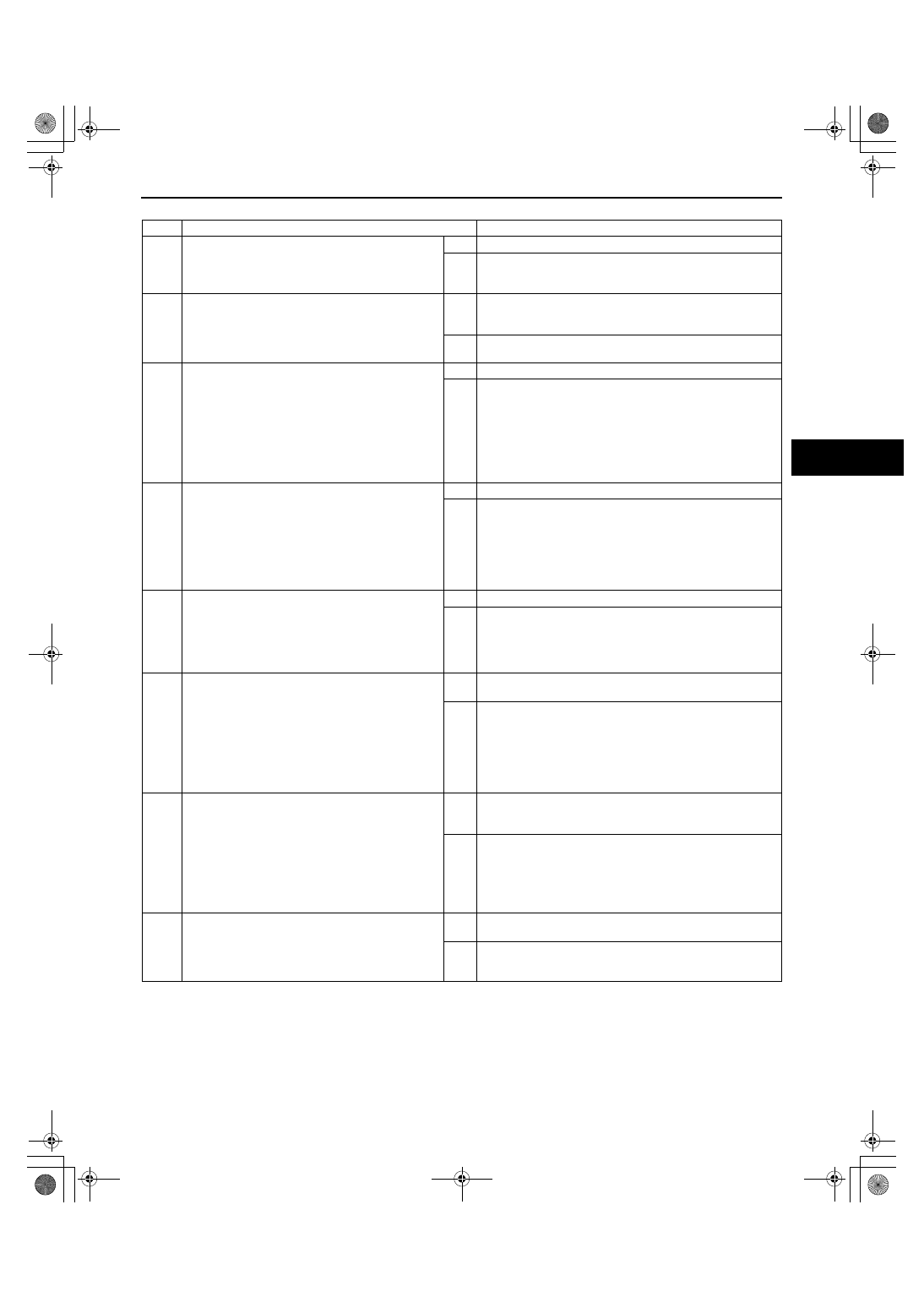
Diagnostic procedure
End Of Sie
STEP
INSPECTION
ACTION
1
VERIFY FREEZE FRAME DATA HAS BEEN
RECORDED
• Has the FREEZE FRAME DATA been
recorded?
Yes
Go to the next step.
No
Record the FREEZE FRAME DATA on the repair order,
then go to the next step.
2
VERIFY RELATED REPAIR INFORMATION
AVAILABILITY
• Verify related Service Bulletins and/or on-line
repair information availability.
• Is any related repair information available?
Yes
Perform repair or diagnosis according to the available
repair information.
• If the vehicle is not repaired, go to the next step.
No
Go to the next step.
3
INSPECT TERMINAL COUPLE COMPONENT
FOR POOR CONNECTION
• Turn the ignition switch to the LOCK position.
• Remove the TCM.
(See 05-17-25 TCM REMOVAL/
INSTALLATION[AW6A-EL, AW6AX-EL].)
• Inspect for poor connection (such as damaged/
pulled-out pins, corrosion).
• Are terminals normal?
Yes
Go to the next step.
No
Replace the couple component, then go to Step 7.
4
INSPECT RESISTANCE OF SHIFT SOLENOID F
CIRCUIT
• Inspect for resistance between couple
component terminals B21 and B16 (wiring
harness-side).
• Is resistancewithin 5.0— 5.6 ohms?
(See 05-17-20 SOLENOID VALVE
INSPECTION[AW6A-EL, AW6AX-EL].)
Yes
Go to go to Step 7.
No
Go to the next step.
5
INSPECT TERMINAL SHIFT SOLENOID F FOR
POOR CONNECTION
• Disconnect the shift solenoid F connector.
• Inspect for poor connection (such as damaged/
pulled-out pins, corrosion).
• Are terminals normal?
Yes
Go to the next step.
No
Replace the couple component, then go to Step 7.
6
INSPECT TERMINAL COUPLE COMPONENT
CIRCUIT FOR SHORT TO POWER
• Inspect for continuity between couple
component terminals (wiring harness-side).
— Terminal B21 and all terminals except B21/
B16
— Terminal B16 and all terminals except B21/
B16
• Is there continuity?
Yes
Repair or replace the couple component, then go to the
next step.
No
Replace the control valve body, then go to the next step.
(See 05-17-38 CONTROL VALVE BODY REMOVAL/
INSTALLATION[AW6A-EL, AW6AX-EL].)
7
VERIFY TROUBLESHOOTING OF DTC P0999
COMPLETED
• Make sure to reconnect all the disconnected
connectors.
• Clear the DTC from the memory using the M-
MDS.
• Drive the vehicle in D range and make sure
that gears shift smoothly from 1GR to 6GR.
• Is same DTC present?
Yes
Replace the TCM, then go to the next step.
(See 05-17-25 TCM REMOVAL/INSTALLATION[AW6A-EL,
AW6AX-EL].)
No
Go to the next step.
8
VERIFY AFTER REPAIR PROCEDURE
• Perform the “After Repair Procedure”.
(See 05-02-4 AFTER REPAIR
PROCEDURE[AW6A-EL, AW6AX-EL].)
• Are any DTCs present?
Yes
Go to the applicable DTC inspection.
(See 05-02-5 DTC TABLE[AW6A-EL, AW6AX-EL].)
No
DTC troubleshooting completed.
1871-1U-06B(05-02).fm 77 ページ 2006年3月15日 水曜日 午前11時18分