Mazda CX 7. Manual - part 206


  Index      Mazda     Mazda CX 7 - service repair manual 2007 year


Search            


Content   ..  204  205  206  207   ..


Mazda CX 7. Manual - part 206


SYMPTOM TROUBLESHOOTING 

04-03–9

04-03

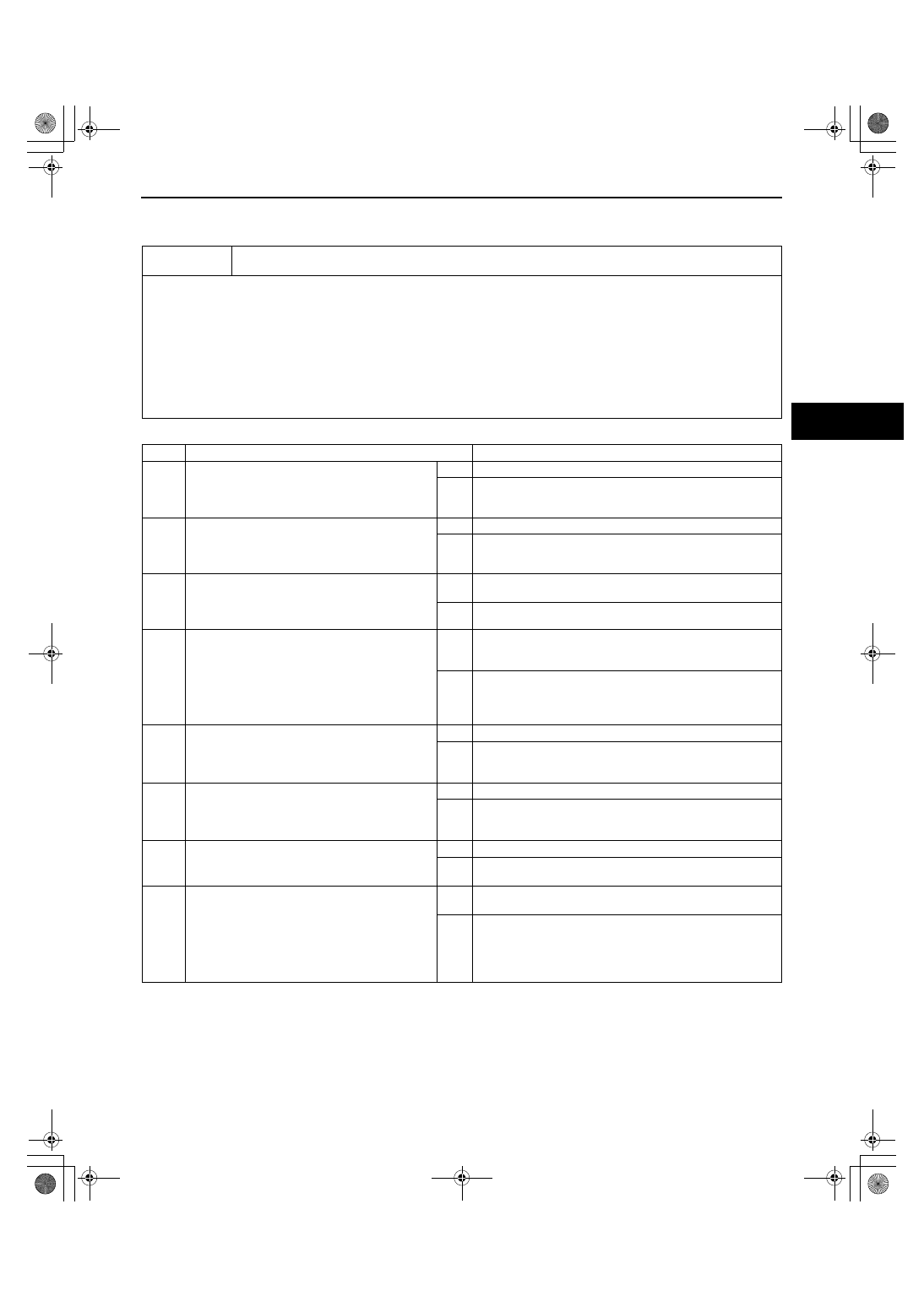
NO.2 ANY OF THE FOLLOWING LIGHTS REMAIN ON: (ABS WARNING LIGHT, BRAKE SYSTEM WARNING 
LIGHT, DSC INDICATOR LIGHT AND/OR TCS OFF LIGHT)

id040300803700

Diagnostic procedure

End Of Sie

2

Any of the following lights remain on: (ABS warning light, BRAKE system warning light, DSC 
indicator light and/or TCS OFF light) 

[TROUBLESHOOTING HINTS]

• Brake fluid amount is low

• Parking brake does not release

• No connection at DSC HU/CM connector

(When DSC HU/CM connector is disconnected, ABS warning light and BRAKE system warning light illuminate)

• DSC HU/CM detected malfunction (Input and output device malfunction)

• DSC HU/CM detects low voltage in power supply

• DSC HU/CM ground malfunction

(When DSC HU/CM ground is not securely connected, ABS warning light and BRAKE system warning light 
illuminate but diagnostic trouble code does not displayed)

• DSC HU/CM does not operate (DSC HU/CM malfunction)

STEP

INSPECTION

ACTION

1

INSPECT BRAKE FLUID AMOUNT AND 
VERIFY THAT PARKING BRAKE RELEASES

• Is the brake fluid amount normal?

• Is the parking brake lever released?

Yes

Go to the next step. 

No

Add brake fluid or release parking brake lever.

2

INSPECT DTCS IN INSTRUMENT CLUSTER

• Inspect the DTC for the instrument cluster 

ON-BOARD DIAGNOSTIC SYSTEM.

• Has DTC U2064 been recorded in memory?

Yes

Go to the next step.

No

Inspect the instrument cluster.
(See 09-22-3 INSTRUMENT CLUSTER INSPECTION.)

3

INSPECT DTCS IN DSC HU/CM

• Inspect the DTC for the DSC ON-BOARD 

DIAGNOSTIC SYSTEM.

• Have DTCs been stored in memory?

Yes

Perform inspection using appropriate DTC.
(See 04-02-3 ON-BOARD DIAGNOSIS.)

No

Go to the next step.

4

INSPECT WHETHER MALFUNCTION IS IN 
CONTROL MODULE CONNECTOR, 
TERMINAL OR OTHER

• Do the ABS warning light and BRAKE 

system warning light go out after 4 s when 
the ignition switch is turned to the ON 
position?

Yes

Temporary poor connection in control module connector.
Inspect DSC HU/CM connector, then go to Step 7.
Inspect DSC HU/CM connector terminal, then go to Step 8.

No

Go to the next step.

5

INSPECT BATTERY

• Is the battery voltage normal?

Yes

Go to the next step.

No

Inspect the battery and charging system.
(See 01-17-2 BATTERY INSPECTION[L3 WITH TC].)
(See 01-17-6 GENERATOR INSPECTION[L3 WITH TC].)

6

INSPECT CHARGING SYSTEM

• Is the battery voltage normal with electrical 

load (A/C, headlight, etc.) on and engine 
idling?

Yes

Go to the next step.

No

Inspect the charging system (drive belt tension, generator, 
etc.).
(See 01-17-6 GENERATOR INSPECTION[L3 WITH TC].)

7

VERIFY THAT DSC HU/CM CONNECTOR IS 
CONNECTED

• Is the DSC HU/CM securely connected?

Yes

Go to the next step.

No

Connect the DSC HU/CM connector securely, then go to the 
next step.

8

VERIFY THAT DSC HU/CM CONNECTOR 
TERMINAL OR RELATED CONNECTOR 
TERMINALS ARE CONNECTED

• Are the DSC HU/CM connector terminal or 

instrument cluster connector terminal etc. 
related connector terminals securely 
connected?

Yes

Replace the DSC HU/CM.
(See 04-15-6 DSC HU/CM REMOVAL/INSTALLATION.)

No

Securely connect the DSC HU/CM connector terminal and 
related connector terminals.

1871-1U-06B(04-03).fm  9 ページ  2006年3月15日 水曜日 午前11時12分

SYMPTOM TROUBLESHOOTING 

04-03–10

NO.3 THERE IS A MALFUNCTION IN THE SYSTEM EVEN THOUGH ABS WARNING LIGHT, BRAKE SYSTEM 
WARNING LIGHT, DSC INDICATOR LIGHT AND TCS OFF LIGHT DO NOT ILLUMINATE

id040300803800

Diagnostic procedure

End Of Sie

NO.4 ABS OR TCS

*1

 OPERATES FREQUENTLY/TCS DOES NOT WORK CORRECTLY

*1

: DSC SYSTEM 

FUNCTION CONTAINS TRACTION CONTROL FUNCTION, DSC INDICATOR LIGHT GOES ON AND OFF 
WHILE DSC IS OPERATING

id040300803400

Diagnostic procedure

End Of Sie

3

There is a malfunction in the system even though the ABS warning light, BRAKE system warning 
light, DSC indicator light and TCS OFF light do not illuminate.

[TROUBLESHOOTING HINTS]

• There is a mechanical malfunction in system

STEP

INSPECTION

ACTION

1

INSPECT DSC HU/CM FOR DTCs

• Inspect the DTC for the DSC ON-BOARD 

DIAGNOSTIC SYSTEM.

• Have DTCs been stored in memory?

Yes

Perform the applicable DTC inspection.
(See 04-02-3 ON-BOARD DIAGNOSIS.)

No

Go to the next step.

2

INSPECT DSC SYSTEM

• Perform DSC system inspection.

(See 04-15-4 DSC SYSTEM INSPECTION.)

• Is the system normal?

Yes

Inspect the conventional brake system.

No

Repair or replace any malfunctioning part.

4

ABS or TCS (*1) operates frequently./TCS does not work correctly.
(*1): DSC system function contains traction control function; DSC indicator light goes on and off 
while DSC is operating.

[TROUBLESHOOTING HINTS]

• There is a difference in size or air pressure between the front and rear tires

• Incorrect ABS wheel-speed signal is input to DSC HU/CM

• There is a malfunction in the engine control system (TCS malfunction)

• Tire problem (low or high air pressure, excessive wear, different grip level by four wheels)

STEP

INSPECTION

ACTION

1

INSPECT DTCS IN DSC HU/CM 

• Inspect the DTC for the DSC ON-BOARD 

DIAGNOSTIC SYSTEM.

• Have DTCs been stored in memory?

Yes

Perform the applicable DTC inspection.
(See 04-02-3 ON-BOARD DIAGNOSIS.)

No

Go to the next step.

2

INSPECT TIRE SIZE AND AIR PRESSURE

• Inspect the tire size and the air pressure.

• Are size and air pressure as specified?

Yes

Go to the next step.

No

Replace with specified tires and adjust tire air pressure.

3

INSPECT ABS WHEEL-SPEED SENSOR 
OUTPUT VALUE

• Inspect the output value from the ABS 

wheel-speed sensor.
(See 04-15-12 FRONT ABS WHEEL-SPEED 
SENSOR INSPECTION.)
(See 04-15-14 REAR ABS WHEEL-SPEED 
SENSOR INSPECTION[2WD].)
(See 04-15-14 REAR ABS WHEEL-SPEED 
SENSOR INSPECTION[AWD].)

• Is the output value normal?

Yes

Go to the next step.

No

• ABS wheel-speed sensor installation inspection: 

Inspect the sensor for looseness and verify that it is 
securely installed.

• Sensor rotor installation inspection:

Inspect the sensor rotor for poor installation and 
chipping of sensor rotor teeth. (If sensor rotor is installed 
poorly, it may cause output of abnormal wave form at 
high speed.)

4

VERIFY THAT TIRE CONDITION

• Verify tire condition for following:

— Wear

— Grip level (different by four wheels)

• Are tires condition okay?

Yes

Find malfunctioning part according to "INTERMITTENT 
CONCERN TROUBLESHOOTING".

No

Adjust, repair or replace tire.

1871-1U-06B(04-03).fm  10 ページ  2006年3月15日 水曜日 午前11時12分

SYMPTOM TROUBLESHOOTING 

04-03–11

NO.5 DSC

*2

 OPERATES FREQUENTLY/DSC DOES NOT WORK CORRECTLY

*2

: DSC INDICATOR LIGHT 

GOES ON AND OFF WHILE DSC IS OPERATING

id040300803500

Diagnostic procedure

End Of Sie

5

DSC (*2) operates frequently. /DSC does not work correctly.
(*2): DSC indicator light goes on and off while DSC is operating.

[TROUBLESHOOTING HINTS]

• DSC HU/CM detected malfunction (input and output device malfunction)

• Poor installation of yaw rate sensor, lateral-G sensor and/or steering angle sensor

(If any of the above sensors are poorly installed, DSC may operate intermittently)

• When replacing the DSC HU/CM, combined sensor or steering angle sensor, initialization is not performed.

(If initialization is not performed correctly, DSC may not work correctly)

STEP

INSPECTION

ACTION

1

INSPECT DSC HU/CM FOR DTCs

• Inspect the DTC for the DSC ON-BOARD 

DIAGNOSTIC SYSTEM.

• Have DTCs been recorded in memory?

Yes

Perform the applicable DTC inspection.
(See 04-02-3 ON-BOARD DIAGNOSIS.)

No

Go to the next step.

2

VERIFY THAT EACH SENSOR IS INSTALLED

• Are the combined sensor and steering angle 

sensor securely installed?

Yes

Go to the next step.

No

Install sensor securely.

*3

VERIFY THAT EACH SENSOR IS INITIALIZED

• Was initialization performed after 

replacement of the DSC HU/CM, combined 
sensor or steering angle sensor?

Yes

Go to the next step.

No

Perform initialization procedure.
(See 04-15-17 COMBINED SENSOR INITIALIZATION 
PROCEDURE.)
(See 09-40-8 STEERING ANGLE SENSOR 
INITIALIZATION PROCEDURE.)

4

VERIFY THAT TIRE CONDITION

• Verify tire condition for following:

— Air pressure

— Wear

— Grip level (different by four wheels)

• Are tires condition okay?

Yes

Find malfunctioning part according to "INTERMITTENT 
CONCERN TROUBLESHOOTING".

No

Adjust, repair or replace tire.

1871-1U-06B(04-03).fm  11 ページ  2006年3月15日 水曜日 午前11時12分


Content   ..  204  205  206  207   ..