Mazda CX 7. Manual - part 200


  Index      Mazda     Mazda CX 7 - service repair manual 2007 year


Search            


Content   ..  198  199  200  201   ..


Mazda CX 7. Manual - part 200


ON-BOARD DIAGNOSTIC 

04-02–15

04-02

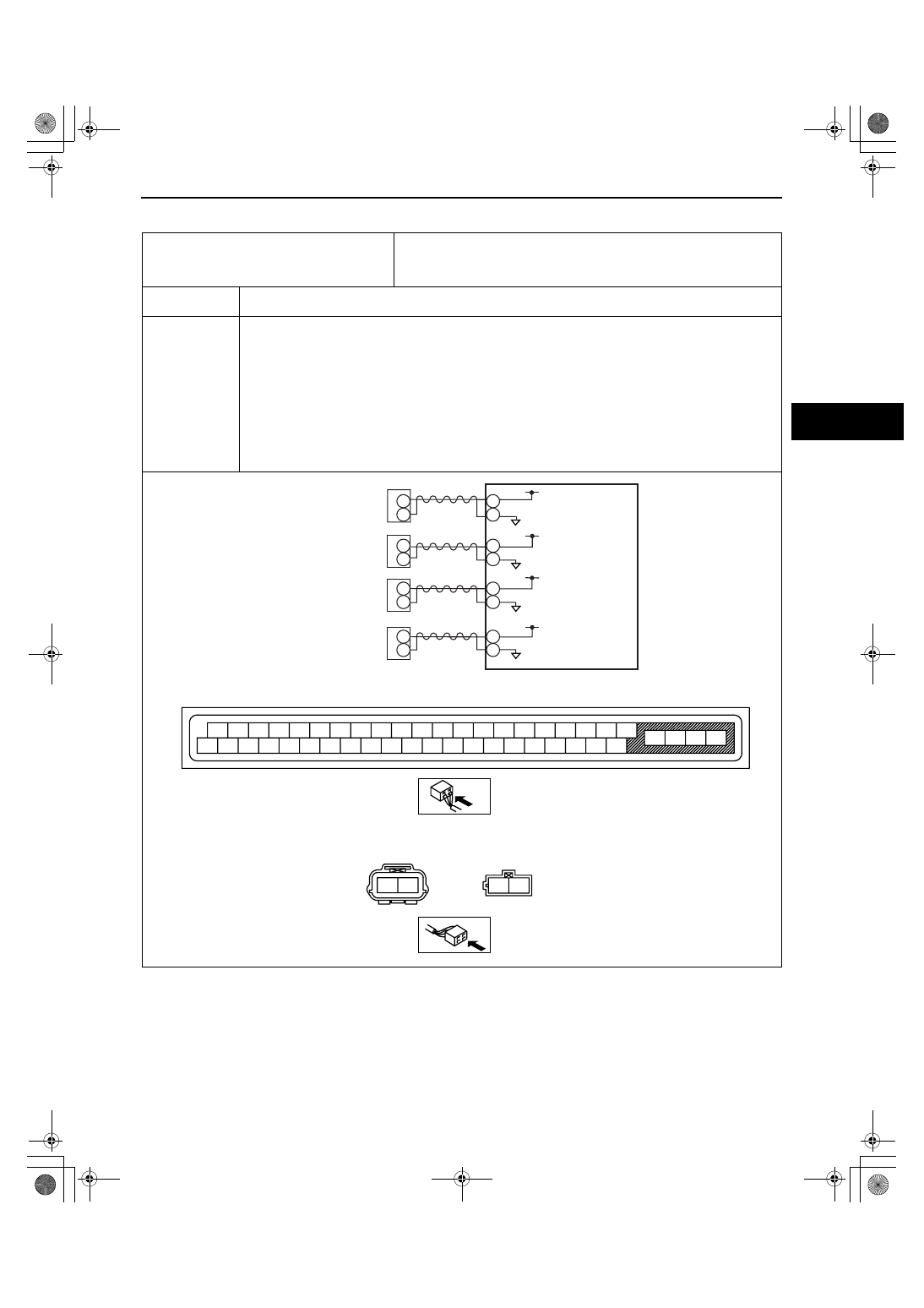
DTC C1145, C1155, C1165, C1175

id040200801100

DTC

C1145
C1155
C1165
C1175

RF ABS wheel-speed sensor (open circuit) system
LF ABS wheel-speed sensor (open circuit) system
RR ABS wheel-speed sensor (open circuit) system
LR ABS wheel-speed sensor (open circuit) system

DETECTION 

CONDITION

• Open circuit has been detected in the ABS wheel-speed sensor or the ABS wheel-speed sensor wiring 

harness on any of the four vehicle wheels.

POSSIBLE 

CAUSE

• Open circuit in the wiring harness between the following DSC HU/CM terminal and the ABS wheel-

speed sensor terminal:
— DSC HU/CM terminal M— RF ABS wheel-speed sensor terminal A

— DSC HU/CM terminal O— RF ABS wheel-speed sensor terminal B

— DSC HU/CM terminal F— LF ABS wheel-speed sensor terminal A

— DSC HU/CM terminal E— LF ABS wheel-speed sensor terminal B

— DSC HU/CM terminal I— RR ABS wheel-speed sensor terminal A

— DSC HU/CM terminal L— RR ABS wheel-speed sensor terminal B

— DSC HU/CM terminal G— LR ABS wheel-speed sensor terminal A

— DSC HU/CM terminal H— LR ABS wheel-speed sensor terminal B

• ABS wheel-speed sensor malfunction

• Poor connection at connectors (female terminal)

A
B

B

A

A

B

G

M
O

H

F
E

L

I

B

A

RF 
ABS WHEEL-SPEED 
SENSOR

LF 
ABS WHEEL-SPEED 
SENSOR

RR 
ABS WHEEL-SPEED 
SENSOR

LR 
ABS WHEEL-SPEED 
SENSOR

DSC  HU/CM

A

B

A

B

ABS WHEEL-SPEED SENSOR WIRING HARNESS-SIDE CONNECTOR

FRONT

REAR

A

B

C

D

F

I

L

O

R

U

X

E

H

Q

T

W

Z

G

J

M

P

S

V

Y

K

N

AA

AB

AC

AD

AE

AF

AG

AH

AI

AJ

AK

AL

AM

AN

AO

AP

AQ

AR

AS

AT

DSC HU/CM WIRING HARNESS-SIDE CONNECTOR

1871-1U-06B(04-02).fm  15 ページ  2006年3月15日 水曜日 午前11時12分

ON-BOARD DIAGNOSTIC 

04-02–16

Diagnostic procedure

End Of Sie

STEP

INSPECTION

ACTION

1

INSPECT PID TO VERIFY THAT WHEEL 
SPEED-SIGNALS ARE TRANSMITTED FROM 
ABS WHEEL- SPEED SENSOR USING M-
MDS

• Turn the ignition switch off.

• Connect the M-MDS to the DLC-2.

• Select the following PIDs using the M-MDS:

WSPD_LF
WSPD_LR
WSPD_RF
WSPD_RR

• Drive the vehicle.

• Verify that the wheel speed-signals are 

transmitted from each ABS wheel-speed 
sensor.

• Are the wheel-speed signals transmitted?

Yes

Go to Step 3.

No

Go to the next step.

2

INSPECT FOR OPEN CIRCUIT IN WIRING 
HARNESS BETWEEN DSC HU/CM AND ABS 
WHEEL-SPEED SENSOR

• Turn the ignition switch off.

• Disconnect the DSC HU/CM connector and 

ABS wheel-speed sensor.

• Inspect for continuity in the wiring harness 

between the following ABS wheel-speed 
sensor connectors on the vehicle wiring 
harness-side and DSC HU/CM connectors.
— RF ABS wheel-speed sensor: M— A

— RF ABS wheel-speed sensor: O— B

— LF ABS wheel-speed sensor: F— A

— LF ABS wheel-speed sensor: E— B

— RR ABS wheel-speed sensor: I— A

— RR ABS wheel-speed sensor: L— B

— LR ABS wheel-speed sensor: G— A

— LR ABS wheel-speed sensor: H— B

• Is there continuity?

Yes

Replace the ABS wheel-speed sensor, then go to the next 
step.
 (See 04-15-11 FRONT ABS WHEEL-SPEED SENSOR 
REMOVAL/INSTALLATION.)
 (See 04-15-13 REAR ABS WHEEL-SPEED SENSOR 
REMOVAL/INSTALLATION[2WD].)
 (See 04-15-13 REAR ABS WHEEL-SPEED SENSOR 
REMOVAL/INSTALLATION[AWD].)

No

Repair or replace the wiring harness, then go to the next 
step.

3

VERIFY THAT THE SAME DTC IS NOT 
PRESENT

• Clear the DTCs from the memory.

 (See 04-02-3 ON-BOARD DIAGNOSIS.)

• Start the engine and drive the vehicle at 10 

km/h {6.2 mph} or more.

• Are the same DTCs present?

Yes

Repeat the inspection from Step 1.
If the malfunction recurs, replace the DSC HU/CM, then go 
to the next step.
 (See 04-15-6 DSC HU/CM REMOVAL/INSTALLATION.)

No

Go to the next step.

4

VERIFY THAT NO OTHER DTCS ARE 
PRESENT

• Are any other DTCs output?

Yes

Go to the applicable DTC inspection.
(See 04-02-3 ON-BOARD DIAGNOSIS.)

No

DTC troubleshooting completed.

1871-1U-06B(04-02).fm  16 ページ  2006年3月15日 水曜日 午前11時12分

ON-BOARD DIAGNOSTIC 

04-02–17

04-02

DTC C1148, C1158, C1168, C1178

id040200801200

DTC

C1148
C1158
C1168
C1178

RF ABS wheel-speed sensor/ABS sensor rotor system
LF ABS wheel-speed sensor/ABS sensor rotor system
RR ABS wheel-speed sensor/ABS sensor rotor system
LR ABS wheel-speed sensor/ABS sensor rotor system

DETECTION 

CONDITION

• Vehicle wheel speed signals of any of the four vehicle wheels indicate abnormal acceleration that 

exceeds specification.

• Vehicle wheel speed signals of any of the four vehicle wheels indicate speed that exceeds specification.

POSSIBLE 

CAUSE

• ABS wheel-speed sensor malfunction (low output, metal shavings on sensor)

• ABS sensor rotor malfunction (chipping of sensor rotor teeth)

• Poor installation of ABS wheel-speed sensor and/or sensor rotor

• Excessive clearance between the ABS wheel-speed sensor and sensor rotor

A
B

B

A

A

B

G

M
O

H

F
E

L

I

B

A

RF 
ABS WHEEL-SPEED 
SENSOR

LF 
ABS WHEEL-SPEED 
SENSOR

RR 
ABS WHEEL-SPEED 
SENSOR

LR 
ABS WHEEL-SPEED 
SENSOR

DSC  HU/CM

A

B

A

B

ABS WHEEL-SPEED SENSOR WIRING HARNESS-SIDE CONNECTOR

FRONT

REAR

A

B

C

D

F

I

L

O

R

U

X

E

H

Q

T

W

Z

G

J

M

P

S

V

Y

K

N

AA

AB

AC

AD

AE

AF

AG

AH

AI

AJ

AK

AL

AM

AN

AO

AP

AQ

AR

AS

AT

DSC HU/CM WIRING HARNESS-SIDE CONNECTOR

1871-1U-06B(04-02).fm  17 ページ  2006年3月15日 水曜日 午前11時12分

ON-BOARD DIAGNOSTIC 

04-02–18

Diagnostic procedure

End Of Sie

STEP

INSPECTION

ACTION

1

INSPECT PID FOR ABNORMAL OUTPUT 
FROM ABS WHEEL-SPEED SENSOR USING 
M-MDS

• Turn the ignition switch off.

• Connect the M-MDS to the DLC-2.

• Select the following PIDs using the M-MDS:

WSPD_LF
WSPD_LR
WSPD_RF
WSPD_RR

• Start the engine and drive the vehicle.

• Verify that the PIDs of the four ABS wheel-

speed sensors correspond approximately.

• Do the vehicle speeds correspond?

Yes

Go to Step 4.

No

If there is a difference in speeds of the four wheels, go to the 
next step.

2

INSPECT IF MALFUNCTION OCCURRED 
DUE TO IMPROPER SENSOR CLEARANCE.

• Inspect the clearance between the ABS 

wheel-speed sensor and the ABS sensor 
rotor.
 (See 04-15-12 FRONT ABS WHEEL-
SPEED SENSOR INSPECTION.)
 (See 04-15-14 REAR ABS WHEEL-SPEED 
SENSOR INSPECTION[2WD].)
 (See 04-15-14 REAR ABS WHEEL-SPEED 
SENSOR INSPECTION[AWD].)

• Is the clearance normal?

Clearance

Front: 0.7— 1.5 mm {0.028— 0.059 in}
Rear: 0.3— 1.1 mm {0.012— 0.043 in} 

Yes

Go to the next step.

No

Replace the ABS wheel-speed sensor, then go to Step 4.
 (See 04-15-11 FRONT ABS WHEEL-SPEED SENSOR 
REMOVAL/INSTALLATION.)
 (See 04-15-13 REAR ABS WHEEL-SPEED SENSOR 
REMOVAL/INSTALLATION[2WD].)
 (See 04-15-13 REAR ABS WHEEL-SPEED SENSOR 
REMOVAL/INSTALLATION[AWD].)

3

VISUALLY INSPECT ABS SENSOR ROTOR 
FOR FOREIGN MATERIAL ADHERING OR 
IMPROPER INSTALLATION

• Is the result normal?

Yes

Go to the next step.

No

Replace the front drive shaft, rear wheel hub component 
(2WD) or rear drive shaft (AWD), then go to the next step.
 (See 03-13-12 FRONT DRIVE SHAFT REMOVAL/
INSTALLATION.)
 (See 03-12-3 WHEEL HUB COMPONENT REMOVAL/
INSTALLATION[2WD].)
 (See 03-13-20 REAR DRIVE SHAFT REMOVAL/
INSTALLATION.)

4

VERIFY THAT THE SAME DTC IS NOT 
PRESENT

• Clear the DTC from the memory.

(See 04-02-3 ON-BOARD DIAGNOSIS.)

• Start the engine and drive the vehicle at 10 

km/h {6.2 mph} or more.

• Are the same DTCs present?

Yes

Repeat the inspection from Step 1.
If the malfunction recurs, replace the DSC HU/CM, then go 
to the next step.
 (See 04-15-6 DSC HU/CM REMOVAL/INSTALLATION.)

No

Go to the next step.

5

VERIFY THAT NO OTHER DTCS ARE 
PRESENT

• Are any other DTCs output?

Yes

Go to the applicable DTC inspection.
(See 04-02-3 ON-BOARD DIAGNOSIS.)

No

DTC troubleshooting completed.

1871-1U-06B(04-02).fm  18 ページ  2006年3月15日 水曜日 午前11時12分


Content   ..  198  199  200  201   ..