Mazda CX 7. Manual - part 138


  Index      Mazda     Mazda CX 7 - service repair manual 2007 year


Search            


Content   ..  136  137  138  139   ..


Mazda CX 7. Manual - part 138


STARTING SYSTEM [L3 WITH TC]

01-19–5

01-19

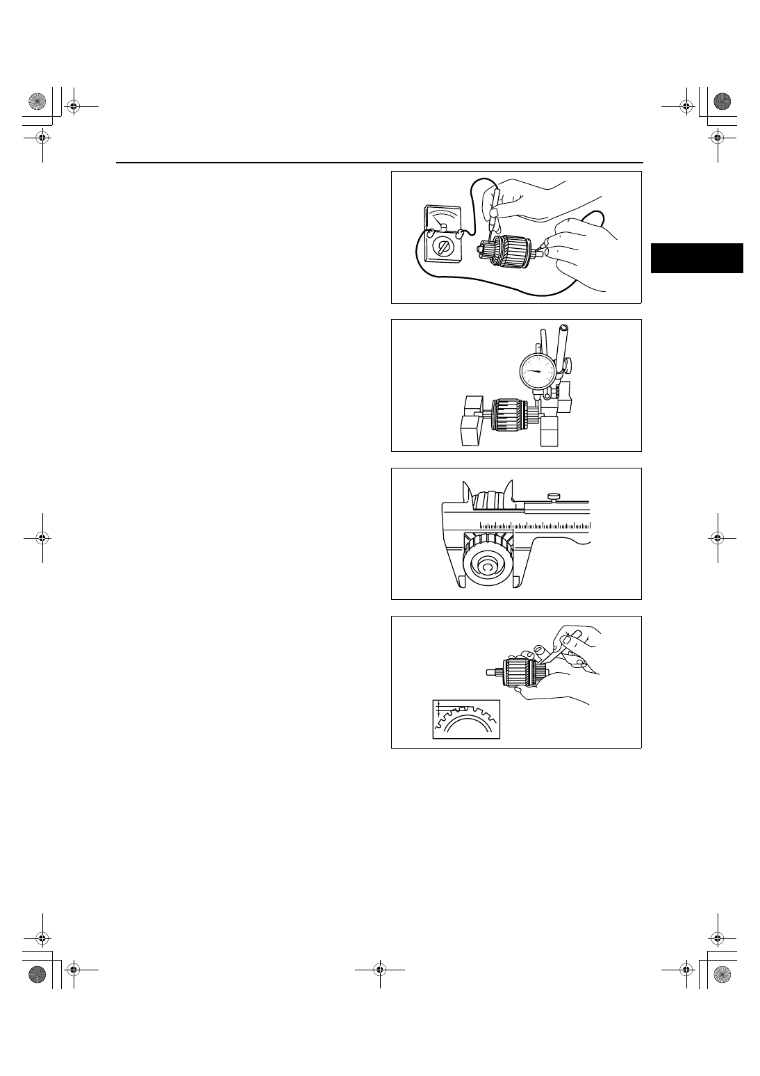
2. Verify that there is no continuity between the 

commutator and the shaft using a tester.

• If there is continuity, replace the armature.

3. Place the armature on V-blocks, and measure the 

runout using a dial indicator.

Starter armature runout

0.05 mm {0.002 in} max.

4. Measure the commutator diameter.

• If not within the minimum specification, 

replace the armature.

Starter commutator diameter

Standard: 29.4 mm {1.16 in}
Minimum: 28.8 mm {1.13 in}

5. Measure the segment groove depth of the 

commutator.

• If not within the minimum specification, 

undercut the grooves to the standard depth.

Segment groove depth of starter commutator

Standard: 0.4— 0.6 mm {0.016— 0.023 in}
Minimum: 0.2 mm {0.008 in}

acxuuw00002045

acxuuw00002046

acxuuw00002047

acxuuw00002048

1871-1U-06B(01-19).fm  5 ページ  2006年3月15日 水曜日 午前10時51分

STARTING SYSTEM [L3 WITH TC]

01-19–6

Magnetic switch

1. Inspect for continuity between terminals S and M 

using a tester.

• If there is no continuity, replace the magnetic 

switch.

2. Inspect for continuity between terminal S and the 

body using a tester.

• If there is no continuity, replace the magnetic 

switch.

3. Verify that there is no continuity between 

terminals M and B using a tester.

• If there is continuity, replace the magnetic 

switch.

Brush and brush holder

1. Verify that there is no continuity between each 

insulated brush and plate using a tester.

• If there is continuity, replace the brush holder.

TERMINAL S

TERMINAL M

acxuuw00002049

TERMINAL S

acxuuw00002050

TERMINAL M

TERMINAL B

acxuuw00002051

acxuuw00002052

1871-1U-06B(01-19).fm  6 ページ  2006年3月15日 水曜日 午前10時51分

STARTING SYSTEM [L3 WITH TC]

01-19–7

01-19

2. Measure the brush length.

• If any brush is worn almost to or beyond the 

minimum specification, replace all of the 
brushes.

Starter brush length

Standard: 12.3 mm {0.48 in}
Minimum: 7.0 mm {0.28 in}

3. Measure the brush spring force using a spring 

balance.

• If not within the minimum specification, 

replace the brush and brush holder 
component.

Starter brush spring force

Standard: 18.3— 24.9 N {1.87— 2.53 kgf, 

4.12— 5.59 lbf}

Minimum: 5.9 N {0.6 kgf, 1.3 lbf}

End Of Sie

STARTER DISASSEMBLY/ASSEMBLY[L3 WITH TC]

id011939800400

1. Disassemble in the order indicated in the table.
2. Assemble in the reverse order of disassembly.

.

MINIMUM
BRUSH
LENGTH

CONTACT FACE WITH COMMUTATOR

acxuuw00002053

acxuuw00002054

N·m {kgf·cm, in·lbf}

2.4—4.4
{25—44, 
22—38}

4.4—7.1
{45—72, 
40—62}

9.8—11.8
{100—120, 
87—104}

4.1—7.6
{42—77, 
37—66}

7

5

4

3

1

2

8

11

9

10

6

acxuuw00002055

1

Magnetic switch

2

Rear housing

3

Brush and brush holder

4

Armature

5

Yoke

6

Planetary gear

7

Front cover

8

Lever

9

Drive pinion

10

Internal gear

11

Gear shaft

1871-1U-06B(01-19).fm  7 ページ  2006年3月15日 水曜日 午前10時51分


Content   ..  136  137  138  139   ..