Mazda CX 7. Manual - part 119


  Index      Mazda     Mazda CX 7 - service repair manual 2007 year


Search            


Content   ..  117  118  119  120   ..


Mazda CX 7. Manual - part 119


INTAKE-AIR SYSTEM [L3 WITH TC]

01-13–15

01-13

Circuit Open/Short Inspection

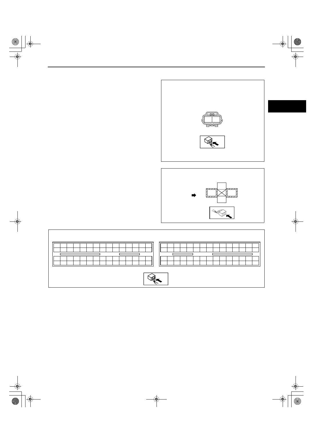
1. Disconnect the PCM connector. (See01-40-6 PCM REMOVAL/INSTALLATION[L3 WITH TC].)
2. Inspect the following wiring harness for an open 

or short circuit (continuity check).

Open circuit

• If there is no continuity, there is an open circuit. Repair or replace the wiring harness.

— Wastegate control solenoid valve terminal B and PCM terminal 2AA

— Wastegate control solenoid valve terminal A and main relay terminal E

Short circuit

• If there is continuity, there is a short circuit. Repair or replace the wiring harness.

— Wastegate control solenoid valve terminal A and body ground

— Wastegate control solenoid valve terminal B and power supply

— Wastegate control solenoid valve terminal B and body ground

End Of Sie

WASTEGATE CONTROL 

SOLENOID VALVE

WIRING HARNESS SIDE CONNECTOR

A

B

acxuuw00000032

FUSE BOX

(MAIN RELAY)

A

E

B

D

FRONT

acxuuw00002335

2BE 2BA 2AW 2AS 2AO 2AK 2AG 2AC 2Y 2U 2Q 2M

2E

2A

2I

2BH 2BD 2AZ 2AV 2AR 2AN 2AJ 2AF 2AB 2X 2T 2P

2H

2D

2L

2BG 2BC 2AY 2AU 2AQ 2AM 2AI 2AE 2AA 2W 2S 2O

2G

2C

2K

2BF 2BB 2AX 2AT 2AP 2AL 2AH 2AD 2Z

2V 2R 2N

2F

2B

2J

1BE 1BA 1AW 1AS 1AO 1AK 1AG 1AC 1Y 1U 1Q 1M

1E

1A

1I

1BH 1BD 1AZ 1AV 1AR 1AN 1AJ 1AF 1AB 1X

1T

1P

1H

1D

1L

1BG 1BC 1AY 1AU 1AQ 1AM 1AI 1AE 1AA 1W 1S 1O

1G

1C

1K

1BF 1BB 1AX 1AT 1AP 1AL 1AH 1AD 1Z

1V

1R 1N

1F

1B

1J

PCM

WIRING HARNESS-SIDE CONNECTOR

acxuuw00000033

1871-1U-06B(01-13).fm  15 ページ  2006年3月15日 水曜日 午前10時44分

INTAKE-AIR SYSTEM [L3 WITH TC]

01-13–16

WASTEGATE ACTUATOR INSPECTION[L3 WITH TC]

id011339800700

1. Remove the air hose and air duct. (See01-13-5 INTAKE AIR SYSTEM REMOVAL/INSTALLATION[L3 WITH 

TC])

2. Disconnect the hose from the wastegate actuator.
3. Plug the wastegate actuator as shown in the 

figure.

4. Connect the vacuum pump to the port

5. Raise the pressure slowly and take a 

measurement of the pressure when the rod stroke 
is 1.5 mm {0.06 in}.

• If the rod does not move, replace the 

turbocharger.

Specification (rod stroke: 1.5 mm {0.06 in})

78.0— 83.4 kPa {586— 625 mmHg, 23.1— 

24.6 inHg}

End Of Sie

WM: TC

PLUG

ROD

WASTEGATE 
ACTUATOR

49 H080 740A

acxuuw00000663

   1.0 
{0.039}

ROD STROKE (mm {in})

 OPERA

TION  PRESSURE

      (kP

a {mmHg, inHg})

110 {825, 32}

100 {750, 30}

90 {675, 27}

80 {600, 24}

70 {525, 21}

60 {450, 18}

   2.0 
{0.079}

  3.0 
{0.12}

  4.0 
{0.16}

  5.0 
{0.20}

  0.0 
 {0.0}

DEPRESSURIZATION

PRESSURIZATION

      WASTEGATE ACTUATOR
 OPERATION CHARACTERISTIC

acxuuw00000664

1871-1U-06B(01-13).fm  16 ページ  2006年3月15日 水曜日 午前10時44分

INTAKE-AIR SYSTEM [L3 WITH TC]

01-13–17

01-13

TURBOCHARGER INSPECTION[L3 WITH TC]

id011339801000

Compressor Wheel Inspection

1. Remove the turbocharger. (See01-13-5 INTAKE AIR SYSTEM REMOVAL/INSTALLATION[L3 WITH TC].)
2. Visually inspect the compressor wheel from view 

A for the cracks, damage, or bending on all the 
compressor wheel blades.

• If there are any cracks or damage, replace the 

turbocharger.

Note

• If there is contact between the compressor 

wheel and compressor housing, there may 
be cracks, damage, or bending on the blade 
end area.

• If there are cracks, damage, or bending on 

the compressor wheel, verify the following 
after replacing the turbocharger.

— Intake air/exhaust system related 

components

— Oil pipe damage

Turbine wheel inspection

1. Remove the turbocharger. (See01-13-5 INTAKE AIR SYSTEM REMOVAL/INSTALLATION[L3 WITH TC].)
2. Visually inspect the turbine wheel from view B for 

the cracks, damage, or bending on all the turbine 
wheel blades.

• If there are cracks, damage, or bending on the 

turbine wheel, replace the turbocharger.

Note

• If there is contact between the turbine wheel 

and turbine housing, there may be cracks, 
damage, or bending on the blade end area.

• If there are cracks, damage, or bending on 

the turbine wheel, verify the following after 
replacing the turbocharger.

— Intake air/exhaust system related 

components

— Oil pipe damage

End Of Sie

WM: ACCELERATOR PEDAL

ACCELERATOR PEDAL REMOVAL/INSTALLATION[L3 WITH TC]

id011339801400

1. Disconnect the negative battery cable.
2. Remove in the order indicated in the table.

3. Install in the reverse order of removal.

End Of Sie

A

COMPRESSOR 
WHEEL

acxuuw00000477

TURBINE WHEEL

B

acxuuw00000478

1

Connector

2

Accelerator pedal

1

2

3

7.8—10.8 {80—110, 69—95}

N·m {kgf·cm, in·lbf}

7.8—10.8 {80—110, 69—95}

acxuuw00002531

1871-1U-06B(01-13).fm  17 ページ  2006年3月15日 水曜日 午前10時44分


Content   ..  117  118  119  120   ..