Mazda CX 7. Manual - part 114
COOLING SYSTEM [L3 WITH TC]
01-12–11
01-12
THERMOSTAT REMOVAL/INSTALLATION[L3 WITH TC]
id011239801200
Warning
• Never remove the cooling system cap or loosen the radiator drain plug while the engine is
running, or when the engine and radiator are hot. Scalding engine coolant and steam may shoot
out and cause serious injury. It may also damage the engine and cooling system.
• Turn off the engine and wait until it is cool. Even then, be very careful when removing the cap.
Wrap a thick cloth around it and slowly turn it counterclockwise to the first stop. Step back while
the pressure escapes.
• When you are sure all the pressure is gone, press down on the cap using the cloth, turn it, and
remove it.
1. Disconnect the negative battery cable.
2. Drain the engine coolant. (See 01-12-5 ENGINE COOLANT REPLACEMENT[L3 WITH TC].)
3. Remove the front splash shield (RH).
4. Remove the charge air cooler duct. (See 01-13-5 INTAKE AIR SYSTEM REMOVAL/INSTALLATION[L3 WITH
TC].)
5. Remove the drive belt. (See 01-10-3 DRIVE BELT REMOVAL/INSTALLATION[L3 WITH TC].)
6. Remove the P/S oil pump with hose and pipe still connected. Position the P/S oil pump out of the way. (See 06-
14-21 POWER STEERING OIL PUMP REMOVAL/INSTALLATION.)
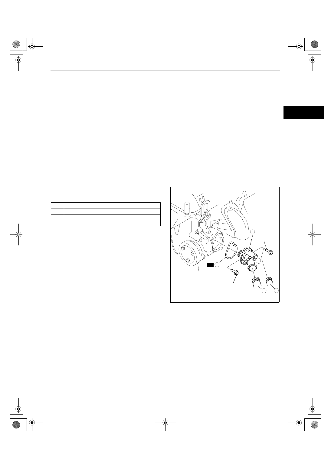
7. Remove in the order indicated in the table.
8. Install in the reverse order of removal.
9. Refill the engine coolant. (See 01-12-5 ENGINE COOLANT REPLACEMENT[L3 WITH TC].)
10. Inspect for engine coolant leakage. (See 01-12-6
ENGINE COOLANT LEAKAGE INSPECTION[L3
WITH TC].).
End Of Sie
THERMOSTAT INSPECTION[L3 WITH TC]
id011239801300
1. Inspect the thermostat for the following.
Warning
• During inspection, the thermostat and water are extremely hot and can cause severe burns. Do not
touch the thermostat and water.
• The valve should not open under normal temperature.
• Opening temperature and valve lift
— If there is a malfunction, replace the thermostat.
Thermostat initial-opening temperature
80— 84
°C {176— 183 °F}
Thermostat full-open temperature
97
°C {207 °F}
Thermostat full-open lift
More than 8.0 mm {0.31 in}
1
Water hose
2
Lower radiator hose
3
Thermostat component
4
Gasket
4
1
2
R
N·m {kgf·cm, in·lbf}
8.0—11.5
{82—117,
71—101}
8.0—11.5
{82—117,
71—101}
3
acxuuw00002011
1871-1U-06B(01-12).fm 11 ページ 2006年3月15日 水曜日 午前10時43分