Mazda CX 7. Manual - part 81
SYMPTOM TROUBLESHOOTING [L3 WITH TC]
01-03–21
01-03
Diagnostic procedure
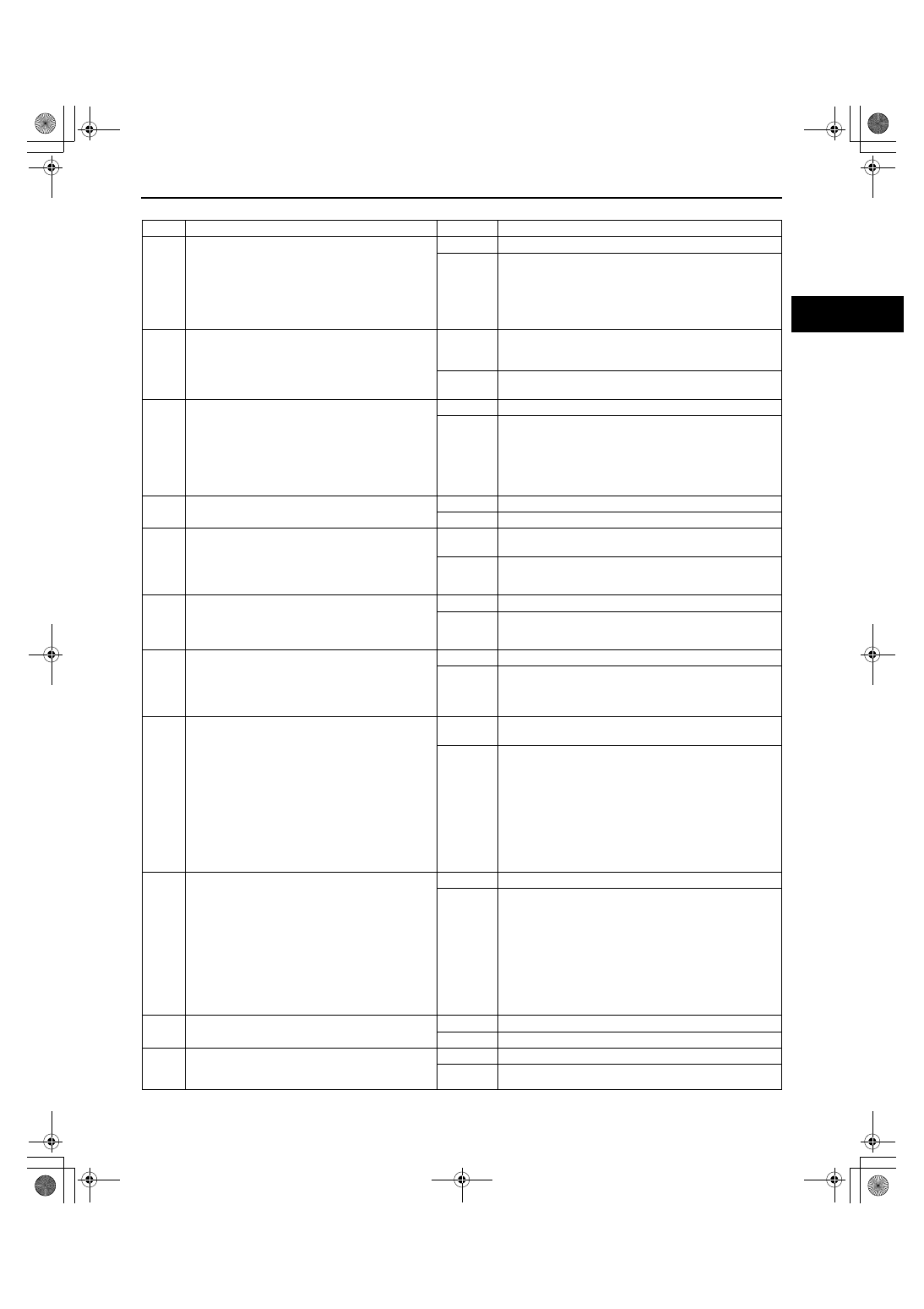
STEP
INSPECTION
RESULTS
ACTION
1
Inspect for the following:
• Fuel quality (proper octane, contamination,
winter/summer blend)
• Fuel leakage
• Intake-air system leakage or restriction
• Vacuum leakage
Are all items normal?
Yes
Go to the next step.
No
Service if necessary.
Repeat Step 1.
2
Perform the self-test function using the M-MDS.
Turn the ignition switch to the ON position.
Retrieve any DTCs.
Is a DTC displayed?
Yes
DTC is displayed:
Go to the appropriate DTC test.
(See01-02-13 DTC TABLE[L3 WITH TC].)
No
No DTC is displayed:
Go to the next step.
3
Access the ECT PID using the M-MDS.
Verify that the ECT PID isless than 116
°C
{241
°F} during driving.
Is the ECT PID less than specified?
Yes
Go to the next step.
No
The cause of this concern could be from the cooling
system overheating.
Perform the symptom troubleshooting “NO.17
COOLING SYSTEM CONCERNS - OVERHEATING.”
(See01-03-60 NO.17 COOLING SYSTEM
CONCERNS-OVERHEATING[L3 WITH TC].)
4
Will the engine run smoothly at part throttle?
Yes
Go to the next step.
No
Go to Step 6.
5
Perform the TP sweep inspection.
(See01-03-78 ENGINE CONTROL SYSTEM
OPERATION INSPECTION[L3 WITH TC].)
Does the electronic throttle control system work
properly?
Yes
Visually inspect the throttle body (damage/scratching.)
If normal, go to the next step.
No
Inspect or replace the malfunctioning parts, according
to the inspection results.
6
Perform the EGR system operation inspection.
(See01-03-78 ENGINE CONTROL SYSTEM
OPERATION INSPECTION[L3 WITH TC].)
Does the EGR system operate properly?
Yes
Go to the next step.
No
Inspect or replace the malfunctioning parts, according
to the inspection results.
7
Perform the Purge Control System Operation
inspection.
(See01-03-78 ENGINE CONTROL SYSTEM
OPERATION INSPECTION[L3 WITH TC].)
Does the purge solenoid valve work properly?
Yes
Go to the next step.
No
Inspect or replace the malfunctioning parts, according
to the inspection results.
8
Inspect the CMP and CKP sensor for the
following;
• Installation condition
(See01-40-45 CAMSHAFT POSITION
(CMP) SENSOR REMOVAL/
INSTALLATION[L3 WITH TC].)
(See01-40-42 CRANKSHAFT POSITION
(CKP) SENSOR REMOVAL/
INSTALLATION[L3 WITH TC].)
• Damaged trigger wheel and camshaft
• Open or short circuit in the wiring harnesses.
Is there any malfunction detected?
Yes
Repair or replace the malfunctioning part according to
the inspection results.
No
Go to the next step.
9
Access and monitor following the PIDs using the
data monitor function.
• ECT
• MAF
• O2S11
• O2S12
• LONGFT1
• SHTFT1
Do the PIDs indicate the correct values under
trouble condition?
(See01-40-6 PCM INSPECTION[L3 WITH TC].)
Yes
Go to the next step.
No
Inspect and repair or replace suspected parts and the
related harnesses.
If the malfunction remains, perform the intermittent
concern troubleshooting.
(See01-03-76 INTERMITTENT CONCERN
TROUBLESHOOTING[L3 WITH TC].)
10
Remove and shake the PCV valve.
Does the PCV valve rattle?
Yes
Go to the next step.
No
Replace the PCV valve.
11
Inspect for restriction in the exhaust system and
the three-way catalytic converter (TWC).
Is there any restriction?
Yes
Replace the malfunctioning part.
No
Go to the next step.
1871-1U-06B(01-03).fm 21 ページ 2006年3月15日 水曜日 午前10時36分