Mazda CX 7. Manual - part 12


  Index      Mazda     Mazda CX 7 - service repair manual 2007 year


Search            


Content   ..  10  11  12  13   ..


Mazda CX 7. Manual - part 12


ON-BOARD DIAGNOSTIC [L3 WITH TC]

01-02–3

01-02

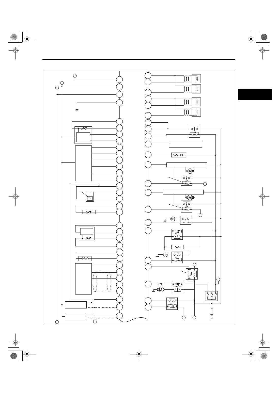
ON-BOARD DIAGNOSTIC WIRING DIAGRAM[L3 WITH TC]

id010239800100

a

a

f

b

b

b

b

c

c

d

e

1BE

1P

1BA

1AY

1AK

1AR

1AV

1AZ

1M

1Y

1Q

2BG

2BB

2BH

2BD

2BC

2BF

2BE

2AZ

1BF

1AX

1AE

1AO

2Q

2C

2D

2N

2I

2R

2P

2M

2Z

2Y

2X

2W

2S

1B

1R

1K

1I

1H

1AW

1AJ

1AC

2AY

2AH

2AV

2AG

2AD

2AC

2AU

1U

1AT

1AA

1BC

PCM

MAF 
SENSOR

APP 
SENSOR

IAT SENSOR

FUEL PRESSURE SENSOR

ECT SENSOR

MAP 
SENSOR

BOOST AIR TEMPERATURE 
SENSOR

HO2S (REAR)

HO2S 
(FRONT)

CKP SENSOR

CMP SENSOR

FUEL INJECTOR 
NO.1

FUEL INJECTOR 
NO.4

FUEL INJECTOR 
NO.3

FUEL INJECTOR 
NO.2

FUEL INJECTOR RELAY

HO2S HEATER (FRONT)

HO2S HEATER (REAR)

FAN CONTROL MODULE NO.1

COOLING FAN
RELAY NO.1

FAN CONTROL MODULE NO.2

COOLING FAN 
RELAY NO.2

A/C RELAY

FUEL PUMP SPEED CONTROL RELAY

FUEL PUMP RESISTOR

FUEL PUMP RELAY

MAIN RELAY

STARTER RELAY

DRIVE-BY-WIRE-RELAY

BATTERY

IGNITION 
SWITCH

acxuuw00002269

1871-1U-06B(01-02).fm  3 ページ  2006年3月15日 水曜日 午前10時32分

ON-BOARD DIAGNOSTIC [L3 WITH TC]

01-02–4

End Of Sie

f

d

e

b

2V

2U

1V

2T

1J

1AS

2AB

2AA

2AS

2AF

2E

2B

2A

2H

2F

2G

1AB

1AF

1AU

2AE

2AK

2AP

2AL

2AO

2AQ

2AM

2AR

2AN

1BB

1BG

1BD

1BH

2BA

2AW

2AX

2AT

2AI

2AJ

1AQ

1AM

1AI

KS

TP SENSOR

BRAKE SWITCH NO.1

BRAKE SWITCH NO.2

VARIABLE SWIRL SHUTTER VALVE SWITCH

REFRIGERANT PRESSURE  SWITCH (HIGH, LOW)

REFRIGERANT PRESSURE  SWITCH (MIDDLE)

PSP SWITCH 

CRUISE CONTROL SWITCH 

GENERATOR

CAN

EGR VALVE

EVAP SYSTEM LEAK 
DETECTION PUMP

PURGE SOLENOID VALVE

WASTEGATE CONTROL 
SOLENOID VALVE

VARIABLE SWIRL 
SOLENOID VALVE

OCV

THROTTLE 
ACTUATOR

SPILL VALVE CONTROL 
SOLENOID VALVE

IGNITION COIL NO.1

IGNITION COIL NO.2

IGNITION COIL NO.3

IGNITION COIL NO.4

GENERATOR

acxuuw00002270

1871-1U-06B(01-02).fm  4 ページ  2006年3月15日 水曜日 午前10時32分

ON-BOARD DIAGNOSTIC [L3 WITH TC]

01-02–5

01-02

MONITORING SYSTEM AND CONTROL SYSTEM DEVICE RELATIONSHIP CHART[L3 WITH TC]

id010239800200

×: Applicable

End Of Sie

Component

Input

Battery

x

x

x

Ignition switch

x

x

x

A/C switch, refrigerant pressure switch (high, low pressure)

x

x

TP sensor

x

x

x

x

x

x

ECT  sensor

x

x

x

x

x

x

x

x

IAT sensor

x

x

x

x

x

x

MAF sensor

x

x

x

x

x

x

x

HO2S (front)

x

x

x

x

HO2S (rear)

x

x

x

x

Fuel gauge sender unit

x

BARO sensor

x

x

MAP sensor

x

CMP sensor

x

CKP  sensor

x

x

x

x

x

x

x

x

VSS

x

x

x

x

Output

Fuel injector

x

HO2S heater (front)

x

HO2S heater (rear)

x

EGR valve

x

Purge solenoid valve

x

x

x

x

EVAP system leak detection pump

x

MIL

x

x

x

x

x

x

x

x

DLC-2

x

x

x

x

x

x

x

x

Oxygen sensor monitor

Oxygen sensor heater monitor

Catalyst monitor

Misfire monitor

Fuel system monitor

Ev

apor

ativ

e system monitor

EGR system monitor

Engine cooling system

1871-1U-06B(01-02).fm  5 ページ  2006年3月15日 水曜日 午前10時32分

ON-BOARD DIAGNOSTIC [L3 WITH TC]

01-02–6

FOREWORD[L3 WITH TC]

id010239800300

• When the customer reports a vehicle malfunction, check the malfunction indicator lamp (MIL) indication and 

diagnostic trouble code (DTC), then diagnose the malfunction according to the following flowchart.

— If a DTC exists, diagnose the applicable DTC inspection. (See 01-02-13 DTC TABLE[L3 WITH TC].)

— If a DTC does not exist and the MIL does not illuminate or flash, diagnose the applicable symptom 

troubleshooting. (See 01-03-8 QUICK DIAGNOSTIC CHART[L3 WITH TC].)

*: Malfunction Indicator Lamp (MIL), Generator Warning Light, Security Light 

End Of Sie

OBD-II PENDING TROUBLE CODE[L3 WITH TC]

id010239800400

• These appear when a problem is detected in a monitored system. The code for a failed system is stored in the 

PCM memory in the first drive cycle. This code is called the pending code. If the PCM determines that the 
system has returned to normal or the problem was mistakenly detected, it deletes the pending code. If the 
problem is found in the second drive cycle, too the PCM determines that the system is malfunctioning, and the 
DTC is stored.

End Of Sie

OBD-II FREEZE FRAME DATA[L3 WITH TC]

id010239800500

• This is technical data which indicates the engine condition at the time of the first malfunction. This data will 

remain in the memory even if another emission-related DTC is stored, with the exception of the Misfire or Fuel 
System DTCs. Once freeze frame data for the Misfire or Fuel System DTC is stored, it will overwrite any 
previous data and the freeze frame will not be overwritten again.

End Of Sie

OBD-II ON-BOARD SYSTEM READINESS TEST[L3 WITH TC]

id010239800600

• This shows the OBD-II systems operating status. If any monitor function is incomplete, the M-MDS will identify 

which monitor function has not been completed. Misfires, Fuel System and Comprehensive Components 
(CCM) are continuous monitoring-type functions. The catalyst, EGR system, evaporation system and oxygen 
sensor will be monitored under drive cycles. The OBD-II diagnostic system is initialized by performing the DTC 
cancellation procedure or disconnecting the negative battery cable.

End Of Sie

OBD-II READ/CLEAR DIAGNOSTIC TEST RESULTS[L3 WITH TC]

id010239800800

• This retrieves all stored DTCs in the PCM and clears the DTC, Freeze Frame Data, On-Board Readiness Test 

Results, Diagnostic Monitoring Test Results and Pending Trouble Codes.

End Of Sie

OBD-II PARAMETER IDENTIFICATION (PID) ACCESS[L3 WITH TC]

id010239800900

• The PID mode allows access to certain data values, analog and digital inputs and outputs, calculated values 

and system status information. Since PID values for output devices are PCM internal data values, inspect each 
device to identify which output devices are malfunctioning.

End Of Sie

CUSTOMER ARRIVES

WARNING LIGHT* 
ON/FLASHING

CHECK FOR 
PRIORITIZED DTC

NO WARNING LIGHT* 
WITH SYMPTOM

•CHECK DTC 
•IGNITION ON TEST, IDLING TEST

DIAGNOSE BY DTC 
(ON-BOARD DIAGNOSTIC) 
•DTC TABLE 
•DTC 
 TROUBLESHOOTING 
 FLOW

DIAGNOSE BY SYMPTOM 
(SYMPTOM TROUBLESHOOTING) 
1. DIAGNOSTIC INDEX 
2. QUICK DIAGNOSIS CHART 
3. SYMPTOM TROUBLESHOOTING

DTC

WITHOUT DTC

acxuuw00002404

1871-1U-06B(01-02).fm  6 ページ  2006年3月15日 水曜日 午前10時32分


Content   ..  10  11  12  13   ..