Mazda CX 7. Manual - part 3


  Index      Mazda     Mazda CX 7 - service repair manual 2007 year


Search            


Content   ..  1  2  3  4  ..


Mazda CX 7. Manual - part 3


GENERAL INFORMATION 

00-00–7

00-00

Procedures for Use
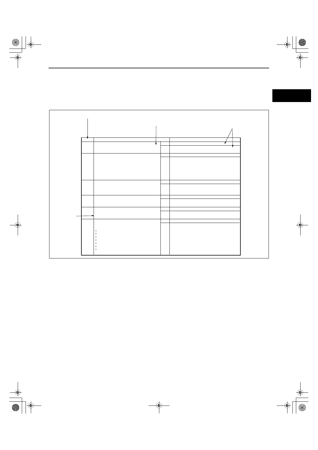
Using the basic inspection (section 05)

• Perform the basic inspection procedure before symptom troubleshooting.

• Perform each step in the order shown.

• The reference column lists the location of the detailed procedure for each basic inspection.

• Although inspections and adjustments are performed according to the reference column procedures, if the 

cause of the malfunction is discovered during basic inspection, continue the procedures as indicated in the 
action column.

BASIC INSPECTION

STEP

INSPECTION

ACTION

1

2

3

4

5

Perform the stall test.
(See 05-13-4 Stall Speed Test.) 
Is the stall speed normal?

Yes

Yes

Yes

Yes

Yes

No

No

No

No

No

Go to the next step.

Go to next step.

Go to the next step.

Go to the next step.

Go to the next step.

REFERENCE 
COLUMN

SHOWS INSPECTION 
ORDER

SHOWS ITEM NAMES FOR 
DETAILED PROCEDURES

SHOW POINTS REQUIRING 
ATTENTION BASED ON 
INSPECTION RESULTS

Repair or replace any malfunctioning parts according to 
the inspection result.

Repair or replace any malfunctioning parts according to 
the inspection result.
Flush ATX and cooler line as necessary.

Repair or replace any malfunctioning parts according to 
the inspection result.

Repair or replace any malfunctioning parts according to 
the inspection result.

Perform the mechanical system test.
(See 05-13-3 MECHANICAL SYSTEM TEST.) 
Is mechanical system normal?

Inspect the ATF color condition.
(See 05-13-8 AUTOMATIC TRANSMISSION 
FLUID (ATF) INSPECTION.)
Are ATF color and odor normal?

Perform the line pressure test. 
(See 05-13-3 Line Pressure Test.)
Is the line pressure normal? 

Turn the ignition switch to the ON position.
When the selector lever is moved, does the selector 
illumination indicate synchronized position to the 
lever location? Also, when other ranges are selected 
from N or P during idling, does the vehicle move 

within 1

2 s?

Inspect the selector lever and TR switch. Repair or 
replace malfunctioning parts.
(See 05-14-5 SELECTOR LEVER INSPECTION.)
(See 05-13-10 TRANSMISSION RANGE (TR) SWITCH
INSPECTION.)
If the selector lever and TR switch are normal, go to the 
next step.

Inspect the voltage at the following TCM terminals.
(See 05-13-29 TCM INSPECTION.)

Terminal 2J (TFT sensor)
Terminals 1D, 2B, 2C, 2E (TR switch)
Terminal 2G (turbine sensor)
Terminal 2D (down switch)
Terminal 2I (up switch)
Terminal 1E (M range switch)
Terminal 1W (steering shift switch)

Is the voltage normal?

Yes

No

Go to the next step.

Repair or replace any malfunctioning parts according to 
the inspection result.

acxuuw00000445

GENERAL INFORMATION 

00-00–8

Using the DTC troubleshooting flow

• DTC troubleshooting flow shows diagnostic procedures, inspection methods, and proper action to take for each 

DTC.

B

E

D

36

88

4

4

4

7

5

6

6

POSSIBLE
CAUSE

1

2

4

3

A

B

C

D

E

1P

DTC P0103

DTC PO103

DETECTION
CONDITION

MAF sensor malfunction

Connector or terminal malfunction
Open circuit in wiring between MAF sensor terminal D and PCM terminal 36

Open circuit in MAF sensor ground circuit

PCM

MAF SENSOR

MAF SENSOR

HARNESS SIDE CONNECTOR

PCM

HARNESS SIDE CONNECTOR

Diagnostic procedure

STEP

INSPECTION

Has FREEZE FRAME DATA been recorded?

VERIFY RELATED REPAIR INFORMATION
AVAILABILITY

Connect diagnostic tool to DLC-2.
Start engine.
Access MAF V PID using diagnostic tool.

Is MAF V PID within 0.2 - 8.3 V?

Turn ignition key to OFF.

Disconnect MAF sensor connector.

Are there any malfunctions?

ACTION

Go to next step.

Yes

No

Yes

No

Yes

No

Yes

If vehicle is not repaired, then go to next step.

Go to next step.

Go to next step.

Repair or replace terminals, then go to Step 8.

POSSIBLE 
CAUSE 
describes 
possible 
point(s) of 
malfunction

Indicates the 
inspection step 
No. to be 
performed
(01 and 05 
section)

STEP shows 
the order of 
troubleshooting

INSPECTION 
describes the 
method to 
quickly 
determine the 
malfunctioning 
part(s).

Reference 
item(s) to 
perform 
ACTION.

ACTION
describes the 
appropriate 
action to be taken  
according to 
the result 
(Yes/No) of the 
INSPECTION.

Indicates the 
connector 
related to the 
inspection

Indicates the 
circuit to be 
inspected 
(01 and 05 
section)

DETECTION CONDITION
describes  the condition 
under which the DTC is 
detected.

Check for poor connection (damaged, pulled-
out terminals, corrosion etc.).

INSPECT POOR CONNECTION OF MAF 
SENSOR CONNECTOR

VERIFY CURRENT INPUT SIGNAL STATUS IS 
CONCERN INTERMITTENT OR CONSTANT

Are related Service Bulletins and/or on-line 
repair information available?

VERIFY FREEZE FRAME DATA HAS BEEN 
RECORDED

Record FREEZE FRAME DATA on repair order, then go 
to next step.

Perform repair or diagnosis according to available repair 
information.

Intermittent concern is existing. Go to INTERMITTENT 
CONCERNS TROUBLESHOOTING procedure. 
(See 01-03-33 INTERMITTENT CONCERN 
TROUBLESHOOTING)

FROM
MAIN RELAY 
TERMINAL D

MIL illuminates if PCM detects the above malfunction during first drive cycle. Therefore, 
PENDING CODE is not available.

FREEZE FRAME DATE is available.
DTC is stored in the PCM memory.

This is a continuous monitor (CCM).

Diagnostic support note

PCM monitors input voltage from TP sensor after ignition key is turned on. If input voltage at PCM terminal 68 is 
above 8.25 V, PCM determines that TP circuit has malfunction.

MAF circuit high input

TROUBLE CONDITION

acxuuw00000446

GENERAL INFORMATION 

00-00–9

00-00

Using the diagnostic index

• Malfunction symptoms are listed in the diagnostic index under symptom troubleshooting.

• The exact malfunction symptoms can be selected by following the index.

No.

TROUBLESHOOTING ITEM

DESCRIPTION

Page

1

Melting of main or other fuses

MIL comes on

(See 01-03-7 NO.2 MIL COMES ON)

(See 01-03-8 NO. 3 WILL NOT CRANK)

5

Engine stalls.

After start/at idle

6

Cranks normally but will not start

7

Slow return to idle 

8

Engine runs rough/rotling

9

Fast idle/runs on

10

Low idle/stalls during deceleration

2

Will not crank

3

4

Hard start/long crank/erratic start/erratic 
crank

Starter cranks engine at normal 
speed but engine requires excessive 
cranking time before starting.

Engine stops unexpectedly at idle 
and/or after start.

(See 01-03-6 MELT NO.1 MAIN OR 
OTHER FUSE)

(See 01-03-9 NO. 4 HARD START/ 
LONG CRANK/ERRATIC CRANK)

(See 01-03-11 NO. 5 ENGINE-STALLS 
AFTER START/AT IDLE)

(See 01-03-15 NO.6 CRANKS 
NORMALLY BUT WILL NOT START)

(See 01-03-19 NO. 7 SLOW RERUN 
TO IDLE)

(See 01-03-20 NO. 8 ENGINE RUNS 
ROUGH/ROLLING IDLE )

(See 01-03-23 NO. 9 FAST IDLE/RUNS 
ON)

(See 01-03-24 NO. 10 LOW IDLE/
STALLS DURING DECELERATION)

Starter cranks engine at normal 
speed but engine will not run. 

Engine takes more time than normal 
to return to idle speed.

Engine speed fluctuates between 
specified idle speed and lower 
speed and engine shakes 
excessively.

Engine speed continues at fast idle 
after warm-up.
Engine runs after ignition key is 
turned to OFF.
Engine stops unexpectedly at begin-
ning of deceleration or recovery 
from deceleration.

MIL is illuminated incorrectly.

Starter does not work.

acxuuw00000447

GENERAL INFORMATION 

00-00–10

Using the quick diagnosis chart

• The chart lists the relation between the symptom and the cause of the malfunction.

• The chart is effective in quickly narrowing down the relation between symptom and cause of the malfunction. It 

also specifies a range of common causes when multiple malfunction symptoms occur.

• The appropriate diagnostic inspection relating to a malfunction cause as specified by the symptoms can be 

selected by looking down the diagnostic inspection column of the chart.

X

X

X

X

X

X

X

X

X

X

X

X

X

X

X

X

X

X

X

X

X

X

X

X

X

X

X

X

X

X

X

X

X

X

X

X

X

X

X

X

X

X

X

X

X

X

X

X

X

X

X

X

X

X

X

X

X

X

X

X

X

X

X

X

X

X

X

X

X

X

X

X

X

X

X

X

X

X

Troubleshooting item

1

Melts of main or other fuse

2

Will not crank

Hard to start/long crank/erratic start/erratic 
crank

4

Cranks normally but will not start

5

Engine stalls

After start/at idle

6

Slow return to idle

7

Engine runs rough/rolling idle

8
9

Engine stalls/quits

Acceleration/cruise

Acceleration/cruise

Acceleration/cruise

Acceleration

Acceleration/cruise

Acceleration/cruise

Acceleration/cruise

Engine runs rough

Acceleration/cruise/
deceleration

Misses

Buck/jerk

Hesitation/stumble

Surges

Lack/loss of power

10

11

Poor fuel economy

12

High oil consumption/leakage

13

Cooling system concerns

Cooling system concerns

Overheating

Runs cold

14

15

16

Engine noise

17

Vibration concerns (engine)

18

A/C always on/ A/C compressor runs 
continuously

A/C does not work sufficiently

19

20

Intermittent concerns

21

Constant voltage

22

Possible factor

MIL comes on

3

Fast idle/runs on

Low idle/stalls during deceleration

Knocking/pinging

Emissions compliance

Exhaust smoke
Fuel odor (in engine compartment)

23

24

25

A/C does not cut off under wide open throttle 
conditions

26

Exhaust sulphur smell

27 Fuel refill concerns
28

Fuel filling shut off issues

29

30
31

Spark plug condition

32

Automatic transaxle 
concerns

Upshift/downshift/
engagement

(See 05-01 AUTOMATIC TRANSAXLE SYMPTOM TROUBLESOOTING)

Starter motor malfunction (Mechanical or 

electrical)

Starter circuit including ignition switch open

Improper engine oil level

Low or dead battery

Charging system malfunction

Improper engine compression

Improper valve timing

Hydrolocked engine

Improper engine oil viscosity

Improper dipstick

Base engine malfunction

Drive plate or flywheel seized

Improper tension or damaged drive belts

Improper engine coolant level

W

ater and anti-freeze mixture improperly

Cooling system malfunction (Radiator

hoses, overflow system, thermostat, etc.)

Cooling fan system malfunction

Engine or transaxle mounts improperly 

installed

Cooling fan or condenser fan seat improperly

Accelerator cable free play mis-adjustment

Fuel quality

PARTS WHICH MAY BE THE
CAUSE OF PROBLEMS

SYMPTOM QUICK DIAGNOSTIC CHART

PART WHICH MAY BE
THE SYMPTOM

CHOOSE THE
ACTUALSYMPTOM

1

2

acxuuw00000448


Content   ..  1  2  3  4  ..