Mazda Protege 5. Manual - part 310


  Index      Mazda     Mazda Protege 5 - service repair manual 2002 year


Search            


Content   ..  308  309  310  311   ..


Mazda Protege 5. Manual - part 310


DOORS AND LIFTGATE 

09–11–4

REAR DOOR ADJUSTMENT

A3U091172010W01

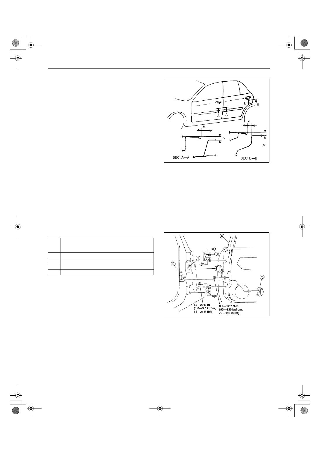
1. Measure the gap and height between the rear 

door and the body.

If not as specified, loosen the door hinge 
installation bolts or the door lock striker 
installation screws, and reposition the door. 
(See 09–11–4 REAR DOOR REMOVAL/
INSTALLATION.) (See 09–14–7 DOOR 
LOCK STRIKER REMOVAL/
INSTALLATION.)

Clearance

a: 3.5—5.5 mm {0.14—0.21 in}
b: –1.0—0.5 mm {–0.040—0.019 in}
c: 3.0—5.0 mm {0.12—0.19 in}
d: –1.0—1.0 mm {–0.040—0.039 in}

2. Tighten the bolts or screws.

End Of Sie

REAR DOOR REMOVAL/INSTALLATION

A3U091172010W02

Warning

••••

Handling the side air bag sensor improperly can accidentally deploy the side air bag module, 
which may seriously injure you. Read AIR BAG SYSTEM SERVICE WARNINGS before working 
around the B-pillar areas. (See 08–10–3 AIR BAG SYSTEM SERVICE WARNINGS.)

Note

The side air bag sensor is located in the B-pillar.

1. Disconnect the negative battery cable.
2. To remove the checker, turn the door screen over.
3. Remove in the order indicated in the table.
4. Install in the reverse order of removal.

5. Adjust the rear door. (See 09–11–4 REAR DOOR 

ADJUSTMENT.)

Z3U0911W004

1

Connector
(See 09–11–5 Connector Removal Note)
(See 09–11–5 Connector Installation Note)

2

Checker pin

3

Rear door hinge

4

Rear door

5

Checker

Z3U0911W003

1712-1U-01G(09-11).fm  4 ページ  2001年6月29日 金曜日 午後12時7分

DOORS AND LIFTGATE 

09–11–5

09–11

Connector Removal Note

1. Pull the pin outward.
2. Disconnect the connector.

Connector Installation Note

1. Push the pin in.
2. Connect the connector.
3. Push the pin in again.

End Of Sie

REAR DOOR DISASSEMBLY/ASSEMBLY

A3U091172010W03

1. Open the rear door glass completely.
2. Disconnect the negative battery cable.
3. Remove the rear door trim. (See 09–17–9 REAR DOOR TRIM REMOVAL/INSTALLATION.)
4. Disassemble in the order indicated in the table.

X3U911WA6

1712-1U-01G(09-11).fm  5 ページ  2001年6月29日 金曜日 午後12時7分

DOORS AND LIFTGATE 

09–11–6

5. Assemble in the reverse order of disassembly.

.

End Of Sie

X3U911WA7

1

Inner handle

2

Door lock knob

3

Door screen

4

Glass guide

5

Door quarter window glass weatherstrip

6

Door quarter window glass

7

Rear door glass

8

Rear power window regulator

9

Glass run channel

10

Rear manual window regulator

11

Rear door lock

12

Outer handle

13

Door weatherstrip

1712-1U-01G(09-11).fm  6 ページ  2001年6月29日 金曜日 午後12時7分

DOORS AND LIFTGATE 

09–11–7

09–11

LIFTGATE REMOVAL/INSTALLATION

A3U091162010W01

Warning

••••

Removing the stay damper without supporting the liftgate can be dangerous. The liftgate may fall 
and injure you. Open the liftgate fully and support it before removing the stay damper.

1. Disconnect the negative battery cable.
2. Remove the headliner. (See 09–17–16 HEADLINER REMOVAL/INSTALLATION.)
3. Remove in the order indicated in the table.

4. Install in the reverse order of removal.
5. Adjust the liftgate. (See09–11–9 LIFTGATE 

ADJUSTMENT)

End Of Sie

1

Connector

2

Rear washer hose

3

Bolt

4

Nut

5

Liftgate

A3U0911W001

1712-1U-01G(09-11).fm  7 ページ  2001年6月29日 金曜日 午後12時7分


Content   ..  308  309  310  311   ..