Mazda Protege 5. Manual - part 293
SYMPTOM TROUBLESHOOTING
08–03–6
End Of Sie
NO.2 AIR BAG SYSTEM WARNING LIGHT ILLUMINATES IMMEDIATELY AFTER IGNITION SWITCH IS
TURNED TO ON POSITION AND REMAINS ILLUMINATED
A3U080301046W05
•
When performing an asterisked(*) troubleshooting inspection, shake the wiring harness and connectors while
doing the inspection to discover the poor contact points which may be the cause of intermittent malfunctions.
•
If there is a problem, check to make sure connectors, terminals and wiring harness are connected correctly and
undamaged.
5
VERIFY WHETHER MALFUNCTION IS IN
PRINT PLATE IN INSTRUMENT CLUSTER
•
Is there continuity between terminals 1J and
1R of print plate on instrument cluster?
Yes
Replace SAS control module, then go to next step.
(See 08–10–12 SAS CONTROL MODULE REMOVAL/
INSTALLATION)
No
Replace instrument cluster, then go to next step.
(See 09–22–3 INSTRUMENT CLUSTER REMOVAL/
INSTALLATION)
6
VERIFY WHETHER MALFUNCTION
SYMPTOM OCCURS AFTER REPAIR OR NOT
•
Connect all SAS control module connectors.
•
Connect driver- and passenger-side pre-
tensioner seat belt connectors.
•
Connect driver- and passenger-side side air
bag module connectors. (Vehicles with side
air bag)
•
Connect passenger-side air bag module
connector.
•
Connect clock spring connector.
•
Connect instrument cluster connector.
•
Connect negative battery cable.
•
Turn ignition switch to ON position.
•
Does air bag system warning light operate
properly?
Yes
Complete troubleshooting, then explain repairs to customer.
No
Recheck malfunction symptoms, then repeat from Step 1 if
malfunction recurs.
STEP
INSPECTION
ACTION
2
Air bag system warning light illuminates immediately after ignition switch is turned to ON position
and remains illuminated.
TROUBLESHOOTING HINTS
•
Malfunction in air bag system warning light circuit
— Instrument cluster (print plate) malfunction
— Malfunction of short bar between SAS control module connector terminals 2W and 2T
— No connection in SAS control module connector
— Short circuit in wiring harness between instrument cluster and SAS control module
— SAS control module malfunction
Note
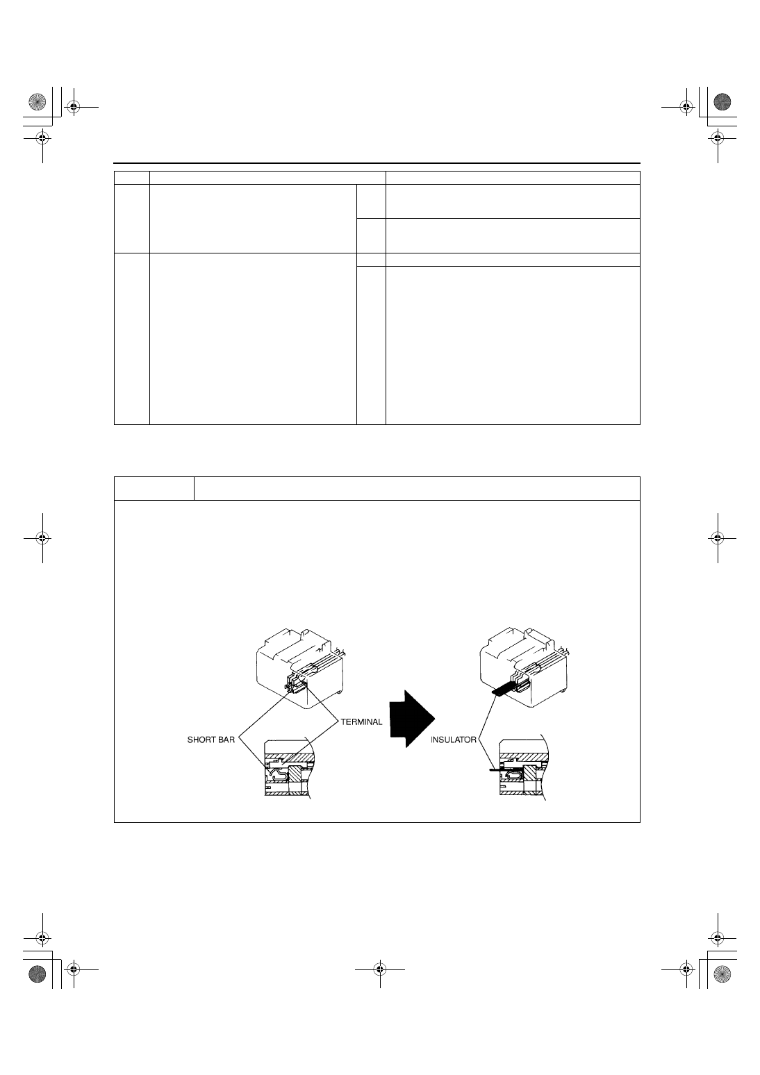
•
When inserting insulator between SAS control module connector terminals and short bar, insert it as shown in the figure.
1712-1U-01G(08-03).fm 6 ページ 2001年6月29日 金曜日 午後3時27分