Mazda Protege 5. Manual - part 271


  Index      Mazda     Mazda Protege 5 - service repair manual 2002 year


Search            


Content   ..  269  270  271  272   ..


Mazda Protege 5. Manual - part 271


SYMPTOM TROUBLESHOOTING 

07–03–3

07–03

End Of Sie

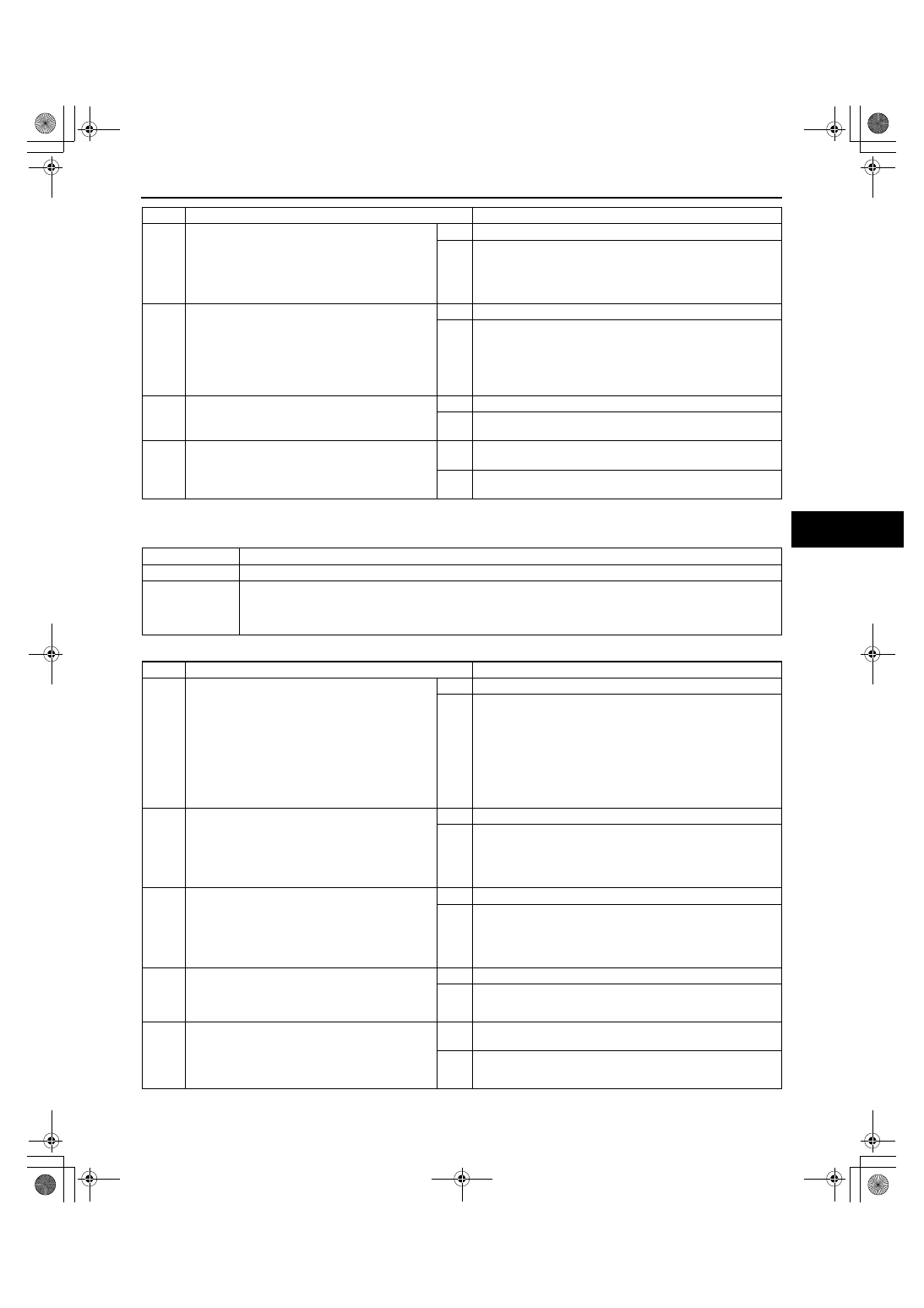
NO.3 AIRFLOW MODE DOES NOT CHANGE

A3U070301038W05

Diagnostic procedure

2

CHECK TO SEE WHETHER MALFUNCTION 
IS IN BLOWER UNIT OR ELSEWHERE

Turn ignition switch to ON position.

Turn fan switch on.

Recirculate air inside vehicle.

Does fan in blower unit rotate smoothly?

Yes

Go to Step 4.

No

Go to next step.

3

INSPECT BLOWER UNIT

Inspect fan in blower unit.
— Is fan free of interference from blower unit 

case?

— Is fan free of foreign material and 

obstructions?

Is fan okay?

Yes

Go to next step.

No

Remove obstruction, repair or replace fan and blower unit 
case, then go to Step 5.

4

INSPECT BLOWER UNIT INTAKE VENT

Is blower unit intake vent clogged?

Yes

Remove obstruction, then go to next step.

No

Inspect if there are any obstructions in passage between 
blower unit and heater unit, then go to next step.

5

VERIFY THAT MALFUNCTION SYMPTOM 
OCCURS AFTER REPAIR

Does air blow out?

Yes

Troubleshooting completed.
Explain repairs to customer.

No

Recheck malfunction symptoms, then repeat from Step 1 if 
malfunction recurs.

STEP

INSPECTION

ACTION

3

Airflow mode does not change.

DESCRIPTION

Malfunction in heater unit and/or climate control unit airflow system.

POSSIBLE 

CAUSE

Heater unit airflow mode link, airflow mode crank, airflow mode rod, airflow mode wire, wire clamp 
malfunction (Steps 1, 2)

Climate control unit rack-and-pinion, airflow mode wire malfunction (Step 3)

Malfunction in one or more heater unit doors (Steps 4, 5)

STEP

INSPECTION

ACTION

1

INSPECT HEATER UNIT AIRFLOW MODE 
SYSTEM

Inspect heater unit airflow mode links, airflow 
mode cranks, airflow mode rods, and wire 
clamp.
— Is there grease on links and cranks?
— Are links, cranks and rods installed 

securely and in the proper position?

— Is wire clamp free of deformation?

Are above items okay?

Yes

Go to next step.

No

Apply grease or install links, cranks and rods securely in 
their proper positions, repair or replace wire clamp, then go 
to Step 6.

2

VERIFY THAT AIRFLOW MODE WIRE FROM 
HEATER UNIT IS POSITIONED SECURELY 
AND CORRECTLY

Is airflow mode wire positioned securely and 
correctly in relation to the heater unit airflow 
mode links?

Yes

Go to next step.

No

Adjust airflow mode wire or install correctly, then go to Step 
6.

3

INSPECT CLIMATE CONTROL UNIT

Inspect climate control unit.
— Is rack-and-pinion properly engaged?
— Is airflow mode wire properly installed in 

correct direction on rack?

Are above items okay?

Yes

Go to next step.

No

Properly engage rack-and-pinion or install airflow mode wire 
in correct direction, then go to Step 6.

4

INSPECT HEATER UNIT AIRFLOW MODE 
DOORS

Is there any foreign material or obstructions 
in any of heater unit doors?

Yes

Remove obstruction, then go to Step 6.

No

Go to next step.

5

VERIFY THAT ALL AIRFLOW MODE DOORS 
WITHIN HEATER UNIT IS POSITIONED 
SECURELY AND PROPERLY

Are all doors within heater unit securely and 
properly positioned?

Yes

Inspect each door for cracks or damage, then go to next 
step.

No

Install malfunction doors securely in proper position, then go 
to next step.

1712-1U-01G(07-03).fm  3 ページ  2001年6月29日 金曜日 午前10時19分

SYMPTOM TROUBLESHOOTING 

07–03–4

End Of Sie

NO.4 NO TEMPERATURE CONTROL WITH CLIMATE CONTROL UNIT

A3U070301038W06

Diagnostic procedure

End Of Sie

6

VERIFY THAT MALFUNCTION SYMPTOM 
OCCURS AFTER REPAIR

Does airflow mode change?

Yes

Troubleshooting completed.
Explain repairs to customer.

No

Recheck malfunction symptoms, then repeat from Step 1 if 
malfunction recurs.

STEP

INSPECTION

ACTION

4

No temperature control with climate control unit.

DESCRIPTION

Malfunction in heater unit and/or climate control unit air mix system.

POSSIBLE 

CAUSE

Heater unit air mix link, air mix crank, air mix rod, air mix wire, wire clamp malfunction (Steps 2, 3)

Climate control unit rack-and-pinion, air mix wire malfunction (Step 4)

Heater unit air mix door malfunction (Steps 5, 6)

Heater piping malfunction (Step 7)

STEP

INSPECTION

ACTION

1

INSPECT COOLANT TEMPERATURE

Is coolant sufficiently warmed up?

Yes

Go to next step.

No

Warm engine up, then go to Step 8.

2

INSPECT HEATER UNIT AIR MIX SYSTEM

Inspect heater unit air mix links, air mix 
cranks, air mix rods, and wire clamp.
— Is there grease on links and cranks?
— Are links, cranks, and rods securely 

installed in their proper positions?

— Is wire clamp free of deformation?

Are above items okay?

Yes

Go to next step.

No

Apply grease or install links, cranks, and rods securely in 
their proper positions, repair or replace wire clamp, then go 
to Step 8.

3

VERIFY THAT AIR MIX WIRE FROM HEATER 
UNIT IS POSITIONED SECURELY AND 
CORRECTLY

Is air mix wire securely installed in the 
correct position in relation to heater unit air 
mix links?

Yes

Go to next step.

No

Adjust air mix wire or install securely in correct position, then 
go to Step 8.

4

INSPECT CLIMATE CONTROL UNIT

Inspect climate control unit.
— Is rack-and-pinion properly engaged?
— Is air mix wire properly installed in correct 

position on rack?

Are above items okay?

Yes

Go to next step.

No

Properly engage rack-and-pinion or install air mix wire in 
correct position, then go to Step 8.

5

INSPECT HEATER UNIT

Is there any foreign material or obstruction in 
heater unit air mix doors?

Yes

Remove obstruction, then go to Step 8.

No

Go to next step.

6

INSPECT HEATER UNIT AIR MIX DOORS

Is heater unit air mix door securely and 
properly installed?

Yes

Inspect air mix door for cracks or damage, then go to next 
step.

No

Install air mix door securely in proper position, then go to 
next step.

7

INSPECT HEATER LINES

Inspect heater lines.
— Is heater piping free of damage and 

cracks?

— Are heater piping connections free of 

engine coolant leakage?

— Are heater piping connections securely 

tightened?

— Are heater piping installation points on 

heater unit free of engine coolant 
leakage?

Are above items okay?

Yes

Operation is okay. Recheck malfunction symptoms.

No

If heater piping connections is loosed, tighten connections 
with specified torque.
Repair or replace heater piping, then go to next step.

8

VERIFY THAT MALFUNCTION SYMPTOM 
OCCURS AFTER REPAIR

Does unit operate in every temperature 
setting?

Yes

Troubleshooting completed.
Explain repairs to customer.

No

Recheck malfunction symptoms, then repeat from Step 1 if 
malfunction recurs.

1712-1U-01G(07-03).fm  4 ページ  2001年6月29日 金曜日 午前10時19分

SYMPTOM TROUBLESHOOTING 

07–03–5

07–03

NO.5 WINDSHIELD FOGGED

A3U070301038W07

When performing an asterisked (*) troubleshooting inspection, shake the wiring harness and connectors while 
doing the inspection to discover whether poor contact points are the cause of any intermittent malfunctions. If 
there is a problem, check to make sure connectors, terminals and wiring harness are connected correctly and 
undamaged.

Diagnostic procedure

5

Windshield fogged.

DESCRIPTION

A/C compressor does not operate while airflow mode is in DEFROSTER or HEAT/DEF modes.

Air intake mode does not change to FRESH while airflow mode is in DEFROSTER or HEAT/DEF 
modes.

POSSIBLE 

CAUSE

Climate control unit (B+ signal) system malfunction (Steps 2, 4, 5)

Air intake actuator malfunction (Steps 3, 7)

Climate control unit (RECIRCULATE, FRESH signal) system malfunction (Steps 9—11)

Malfunction in blower unit air intake doors (Steps 12, 13)

STEP

INSPECTION

ACTION

1

COOL AIR BLOW OUT INSPECTION

When both A/C and fan switch in climate 
control unit are on, does cool air blow out 
from front vent?

Yes

Go to next step.

No

Go to Step 1 of troubleshooting index No.7.

2

INSPECT CLIMATE CONTROL UNIT POWER 
SUPPLY FUSE FOR B+ SIGNAL

Is climate control unit power supply fuse for 
B+ signal okay?

Yes

Go to next step.

No

Inspect for a short to ground on blown fuse circuit.

Repair or replace as necessary. Install appropriate 
amperage fuse.

3

INSPECT AIR INTAKE ACTUATOR

Inspect air intake actuator.
— Is there grease on link?
— Is link securely and properly positioned?
— Is link free of obstructions?

Are above items okay?

Yes

Go to next step.

No

Apply grease or install link properly and securely, remove 
obstruction, then go to Step 14.

*4

INSPECT WIRING HARNESS BETWEEN 
FUSE BLOCK AND CLIMATE CONTROL UNIT 
FOR CONTINUITY

Disconnect climate control unit connector 
(12-pin).

Turn ignition switch to ON position.

Test voltage at climate control unit connector 
terminal K (B+ signal).

Is voltage approximately 12 V?

Yes

Go to next step.

No

Repair wiring harness between fuse block and climate 
control unit, then go to Step 14.

*5

INSPECT WIRING HARNESS BETWEEN 
CLIMATE CONTROL UNIT AND GROUND 
FOR VOLTAGE

Test voltage at climate control unit connector 
terminal E (Ground).

Is voltage approximately 0V?

Yes

Go to next step.

No

Repair wiring harness between climate control unit and 
ground, then go to Step 14.

6

VERIFY WHETHER MALFUNCTION IS IN 
BLOWER UNIT AIR INTAKE DOOR OR 
ELSEWHERE

Turn ignition switch to LOCK position.

Connect climate control unit connector (12-
pin).

Remove air intake actuator.

Turn ignition switch to ON position.

Set fan switch to 4th position.

Does air intake mode (RECIRCULATE, 
FRESH) change smoothly when air intake 
link is operated by hand?

Yes

Go to next step.

No

Go to Step 12.

7

INSPECT AIR INTAKE ACTUATOR

Inspect air intake actuator.
(See 07–40–4 AIR INTAKE ACTUATOR 
INSPECTION)

Is it okay?

Yes

Go to next step.

No

Replace air intake actuator, go to Step 14.

1712-1U-01G(07-03).fm  5 ページ  2001年6月29日 金曜日 午前10時19分

SYMPTOM TROUBLESHOOTING 

07–03–6

End Of Sie

NO.6 AIR FROM VENTS NOT COLD ENOUGH

A3U070301038W08

Diagnostic procedure

8

INSPECT AIR INTAKE SELECTOR SWITCH 
AND MICROSWITCH IN CLIMATE CONTROL 
UNIT

Test voltage at climate control unit connector 
(12-pin) terminals A and I.

Is it okay?

Yes

Go to next step.

No

Replace climate control unit, then go to Step 14.

*9

INSPECT WIRING HARNESS BETWEEN 
CLIMATE CONTROL UNIT AND AIR INTAKE 
ACTUATOR FOR CONTINUITY

Turn ignition switch to LOCK position.

Is there continuity between following climate 
control unit connector (12-pin) terminal and 
air intake actuator connector terminal?
— Terminal A —Terminal F (FRESH signal)
— Terminal I —Terminal A (RECIRCULATE 

signal)

Yes

Go to next step.

No

Repair wiring harness between climate control unit and air 
intake actuator, then go to Step 14.

*10

INSPECT WIRING HARNESS BETWEEN 
CLIMATE CONTROL UNIT AND AIR INTAKE 
ACTUATOR FOR SHORT TO GROUND

Is there continuity between following climate 
control unit connector (12-pin) terminal and 
ground?
— Terminal A (FRESH signal)
— Terminal I (RECIRCULATE signal)

Yes

Repair wiring harness between climate control unit and air 
intake actuator, then go to Step 14.

No

Go to next step.

*11

INSPECT WIRING HARNESS BETWEEN 
CLIMATE CONTROL UNIT AND AIR INTAKE 
ACTUATOR FOR SHORT TO B+

Turn ignition switch to ON position

Test voltage at following climate control unit 
connector (12-pin) terminal.
— Terminal A (FRESH signal)
— Terminal I (RECIRCULATE signal)

Is voltage approximately 12 V?

Yes

Repair wiring harness between climate control unit and air 
intake actuator, then go to Step 14.

No

Replace climate control unit, then go to Step 14.

12

INSPECT BLOWER UNIT AIR INTAKE DOOR

Is there any foreign material or obstruction in 
blower unit air intake door?

Yes

Remove obstruction, then go to Step 14.

No

Go to next step.

13

VERIFY THAT BLOWER UNIT AIR INTAKE 
DOOR IS POSITIONED SECURELY AND 
PROPERLY

Is blower unit air intake door securely and 
properly positioned?

Yes

Inspect air intake door for cracks or damage, then go to next 
step.

No

Install air intake door securely in proper position, then go to 
next step.

14

VERIFY THAT MALFUNCTION SYMPTOM 
OCCURS AFTER REPAIR

Does malfunction disappear?

Yes

Troubleshooting completed.
Explain repairs to customer.

No

Recheck malfunction symptoms, then repeat from Step 1 if 
malfunction recurs.

STEP

INSPECTION

ACTION

6

Air from vents not cold enough.

DESCRIPTION

Magnetic clutch operates but A/C system malfunctions.

POSSIBLE 

CAUSE

Drive belt malfunction (Step 2)

Malfunction in blower unit or condenser (Steps 4, 5)

Malfunction in receiver/drier or expansion valve (valve closes too much) (Steps 8, 9)

Malfunction in refrigerant lines (Steps 10, 11)

A/C compressor system malfunction, insufficient compressor oil (Steps 15, 16)

Over filling of compressor oil, malfunction in expansion valve or heater unit air mix link system (Steps 
17—19)

STEP

INSPECTION

ACTION

1

INSPECT DRIVE BELT

Inspect drive belt.
(See 01–10B–3 DRIVE BELT INSPECTION 
[FS])

Is it okay?

Yes

Go to next step.

No

Adjust or replace drive belt, then go to Step 20.
(See 01–10B–4 DRIVE BELT ADJUSTMENT [FS])

1712-1U-01G(07-03).fm  6 ページ  2001年6月29日 金曜日 午前10時19分


Content   ..  269  270  271  272   ..