Mazda Protege 5. Manual - part 253


  Index      Mazda     Mazda Protege 5 - service repair manual 2002 year


Search            


Content   ..  251  252  253  254   ..


Mazda Protege 5. Manual - part 253


AUTOMATIC TRANSAXLE 

05–17–21

05–17

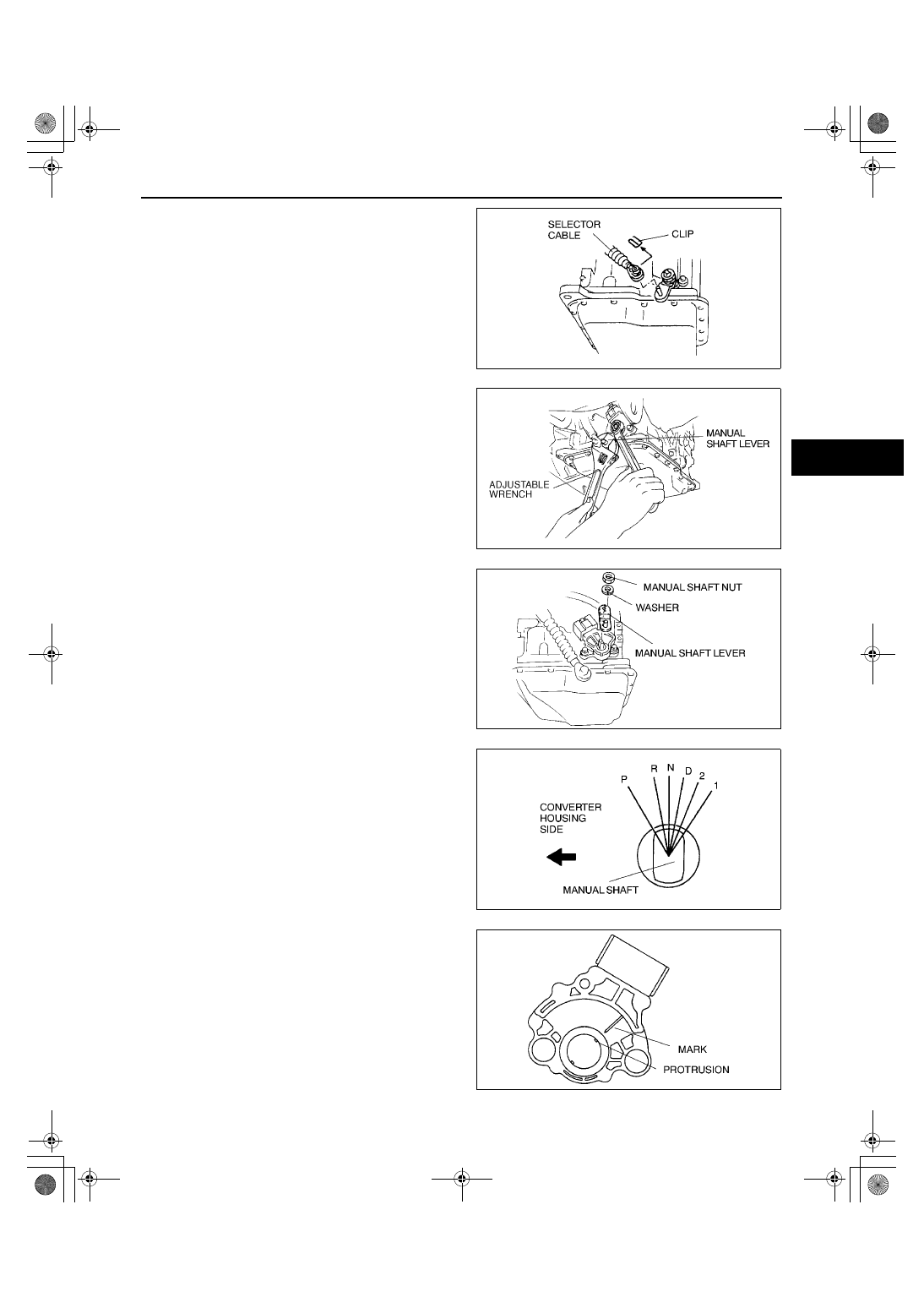
5. Remove the clip and disconnect the selector 

cable.

Caution

••••

Do not use an impact wrench. Hold the 
manual shaft lever when removing the 
manual shaft nut, or the transaxle may be 
damaged.

6. Set the adjustable wrench as shown to hold the 

manual shaft lever.

7. Remove the manual shaft nut and washer.

8. Remove the manual shaft lever.
9. Remove the TR switch.

10. Rotate the manual shaft to the converter housing 

side fully, then return 2 notches to set the N 
position.

11. Align the protrusion and mark as shown.

X3U517WAC

Y3U517WAM

X3U517WAD

X3U517WAE

X3U517WCW

1712-1U-01G(05-17).fm  21 ページ  2001年6月29日 金曜日 午前10時12分

AUTOMATIC TRANSAXLE 

05–17–22

12. Install the TR switch while aligning the protrusion 

and groove as shown.

13. Turn the TR switch so that the neutral hole is in 

line with the flat, straight surfaces on either side of 
the manual shaft.

14. Hand-tighten the TR switch bolts.
15. Perform the TR switch adjustment. (See 05–17–

23 TRANSAXLE RANGE (TR) SWITCH 
ADJUSTMENT.)

16. Install the manual shaft lever and washer.

Caution

••••

Do not use an impact wrench. Hold the 
manual shaft lever when tightening the 
manual shaft nut, or the transaxle may be 
damaged.

17. Set the adjustable wrench as shown to hold the manual shaft lever.
18. Tighten the manual shaft nut using a torque 

wrench.

Tightening torque

32—46 N·m {3.2—4.7 kgf·m, 24—33 ft·lbf}

19. Install the clip as shown in the figure.

X3U517WCX

X3U517WAF

X3U517WAJ

X3U517WCZ

1712-1U-01G(05-17).fm  22 ページ  2001年6月29日 金曜日 午前10時12分

AUTOMATIC TRANSAXLE 

05–17–23

05–17

20. Verify that the selector lever range position and 

TR switch are aligned, then connect the selector 
cable.

21. Inspect for continuity at the TR switch. (See 05–

17–20 Inspection of Continuity.)

22. Connect the TR switch connector.
23. Install the splash shield.
24. Install the air cleaner component and fresh-air 

duct. (See 01–13A–5 INTAKE-AIR SYSTEM 
REMOVAL/INSTALLATION [ZM].) (See 01–13B–
6 INTAKE-AIR SYSTEM REMOVAL/
INSTALLATION [FS].)

25. Connect the negative battery cable.
26. Inspect operation of the TR switch. (See 05–17–

20 Inspection of Operation.)

End Of Sie

TRANSAXLE RANGE (TR) SWITCH ADJUSTMENT

A3U051719440W03

1. Disconnect the negative battery cable.
2. Remove the fresh-air duct and air cleaner component. (See 01–13A–5 INTAKE-AIR SYSTEM REMOVAL/

INSTALLATION [ZM].) (See 01–13B–6 INTAKE-AIR SYSTEM REMOVAL/INSTALLATION [FS].)

3. Remove the splash shield.
4. Remove the clip and disconnect the selector 

cable.

5. Rotate the manual shaft to the converter housing 

side fully, then return 2 notches to set the N 
position.

6. Disconnect the TR switch connector.

X3U517WAK

X3U517WD0

X3U517WD3

X3U517WAL

1712-1U-01G(05-17).fm  23 ページ  2001年6月29日 金曜日 午前10時12分

AUTOMATIC TRANSAXLE 

05–17–24

7. Loosen the TR switch mounting bolts.

8. Connect an ohmmeter between terminals B and 

H.

9. Adjust the switch to the point where there is 

continuity between the terminals.

10. Tighten the TR switch mounting bolts.

Tightening torque

7.9—10.7 N·m {80—110 kgf·cm, 69.5—95.4 

in·lbf}

11. Verify that the selector lever range position and 

TR switch are aligned.

12. Connect the TR switch connector.
13. Install the clip as shown in the figure.

14. Connect the selector cable.
15. Install the splash shield.
16. Install the air cleaner component and fresh-air 

duct. (See 01–13A–5 INTAKE-AIR SYSTEM 
REMOVAL/INSTALLATION [ZM].) (See 01–13B–
6 INTAKE-AIR SYSTEM REMOVAL/
INSTALLATION [FS].)

17. Connect the negative battery cable.

End Of Sie

X3U517WAM

Z3U517W15

X3U517WD1

X3U517WD2

1712-1U-01G(05-17).fm  24 ページ  2001年6月29日 金曜日 午前10時12分


Content   ..  251  252  253  254   ..