Mazda Protege 5. Manual - part 245


  Index      Mazda     Mazda Protege 5 - service repair manual 2002 year


Search            


Content   ..  243  244  245  246   ..


Mazda Protege 5. Manual - part 245


MANUAL TRANSAXLE [F25M-R]

05–15A–3

05–15A

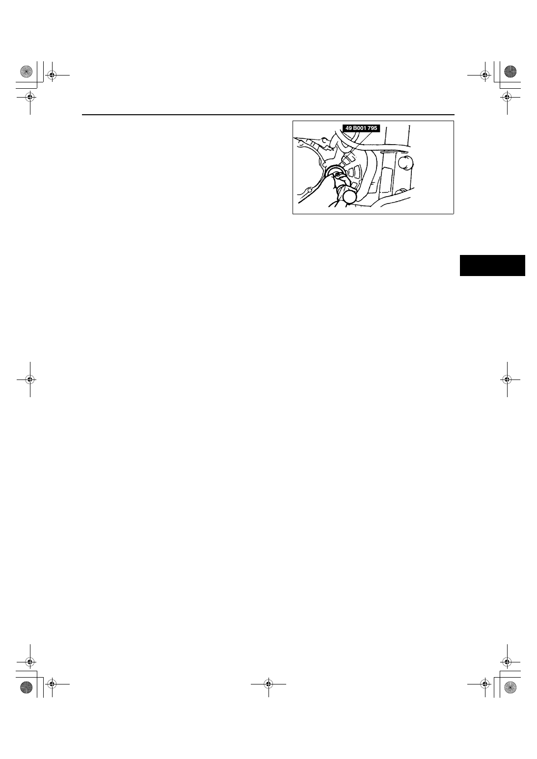
4. Using the SST and a hammer, tap the new oil seal in 

evenly until the SST contacts the transaxle case.

5. Coat the oil seal lip with transaxle oil.
6. Insert the drive shaft and joint shaft to the transaxle. 

(See 03–13–3 JOINT SHAFT REMOVAL/
INSTALLATION.) (See 03–13–9 DRIVE SHAFT 
REMOVAL/INSTALLATION.)

7. Add the specified amount and type of transaxle oil.

(See 05–15A–2 TRANSAXLE OIL REPLACEMENT 
[F25M-R].)

End Of Sie

U3U51503

1712-1U-01G(05-15A).fm  3 ページ  2001年6月29日 金曜日 午前10時10分

MANUAL TRANSAXLE [F25M-R]

05–15A–4

MANUAL TRANSAXLE (MTX) REMOVAL/INSTALLATION [F25M-R]

A3U051501029W01

1. Remove the battery, battery cover, and battery tray.
2. Remove the fresh-air duct and air cleaner component.
3. Remove the wheels and tires and splash shields.
4. Remove the EGR pipe, front pipe and TWC. (See 01–15–1 EXHAUST SYSTEM REMOVAL/INSTALLATION.)
5. Drain the transaxle oil into a container.
6. Remove the starter. (See 01–19–1 STARTER REMOVAL/INSTALLATION.)
7. Remove in the order indicated in the table.
8. Install in the reverse order of removal.
9. Add the specified amount of the specified transaxle oil. (See 05–15A–2 TRANSAXLE OIL REPLACEMENT 

[F25M-R].)

10. Warm up the engine and transaxle, inspect for oil leakage, and inspect the transaxle operation.

.

A3U0515W005

1

Speedometer sensor connector

2

Neutral switch connector

3

Back-up light switch connector

4

Clutch release cylinder

5

Extension bar

6

Change control rod

7

Tie-rod end ball joint
(See 06–12–9 STEERING GEAR AND LINKAGE 
REMOVAL/INSTALLATION.)

8

Lower arm ball joint
(See 05–15A–5 Lower Arm Ball Joint Removal 
Note.)

1712-1U-01G(05-15A).fm  4 ページ  2001年6月29日 金曜日 午前10時10分

MANUAL TRANSAXLE [F25M-R]

05–15A–5

05–15A

Lower Arm Ball Joint Removal Note

Caution

••••

Wrap a rag around the ball joint dust seal to protect it from getting damages.

1. Pry the lower arm out of the knuckle.

No.4 Engine Mount Bracket Removal Note

1. Support the engine using the SST before removing the No.4 engine mount bracket.
2. Remove the No.4 engine mount bracket.

Manual Transaxle (MTX) Removal Note

1. Loosen the SST (49 E017 5A0) and lean the engine toward the transaxle.
2. Support the transaxle on a jack.
3. Remove the transaxle mounting bolts.
4. Remove the transaxle.

9

Drive shaft
(See 03–13–9 DRIVE SHAFT REMOVAL/
INSTALLATION.)

10

Joint shaft
(See 03–13–3 JOINT SHAFT REMOVAL/
INSTALLATION.)

11

No.4 engine mount bracket
(See 05–15A–5 No.4 Engine Mount Bracket 
Removal Note.)

12

Engine mount member
(See 05–15A–6 Engine Mount Member Installation 
Note.)

13

No.2 engine mount

14

No.1 engine mount bracket

15

MTX
(See 05–15A–5 Manual Transaxle (MTX) Removal 
Note.)
(See 05–15A–6 Manual Transaxle (MTX) 
Installation Note.)

X3U515WA4

Z3U110WFK

X3U515WA6

1712-1U-01G(05-15A).fm  5 ページ  2001年6月29日 金曜日 午前10時10分

MANUAL TRANSAXLE [F25M-R]

05–15A–6

Manual Transaxle (MTX) Installation Note

1. Set the transaxle on a jack and lift into place.
2. Install the transaxle mounting bolts.

Engine Mount Member Installation Note

1. Verify that the engine mount rubbers are installed 

as shown.

2. Put the No.2 engine mount stud bolts in the 

installation holes when installing the engine 
mount member.

3. Tighten bolt A and nut B.

Tightening torque

Bolt A: 67—89 N·m {6.8—9.1 kgf·m, 50—65 

ft·lbf}

Nut B: 67—93 N·m {6.8—9.5 kgf·m, 50—68 

ft·lbf}

4. Tighten nuts C.

Tightening torque

Nut C: 67—93 N·m {6.8—9.5 kgf·m, 50—68 ft·lbf}

5. By aligning the holes with the stud bolts, install 

the No.4 engine mount bracket to the transaxle.

6. Align the hole of the No.4 engine mount bracket 

with the No.4 engine mount rubber on vehicle, 
and temporarily tighten bolt D.

7. Tighten nuts E, then bolt D.

Tightening torque

Bolt D and nut E: 67—93 N·m {6.8—9.5 

kgf·m, 50—68 ft·lbf}

8. Remove the SST (49 E017 5A0).

End Of Sie

X3U515WA7

X3U515WA8

X3U515WA9

X3U515WB0

1712-1U-01G(05-15A).fm  6 ページ  2001年6月29日 金曜日 午前10時10分


Content   ..  243  244  245  246   ..