Mazda Protege 5. Manual - part 171
CONTROL SYSTEM [ZM]
01–40A–37
01–40A
Circuit Open/Short Inspection
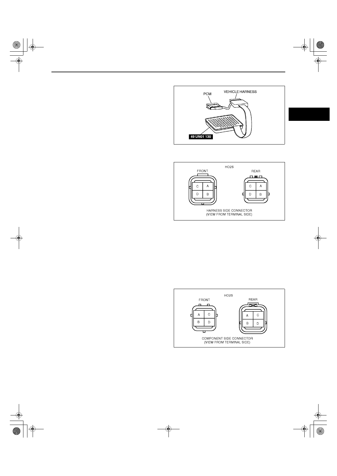
1. Remove the PCM. (See 01–40A–7 PCM REMOVAL/INSTALLATION [ZM].)
2. Connect the SST (104 Pin Breakout Box) to the
PCM as shown.
3. Tighten the connector attaching screw.
Tightening torque
7.9—10.7 N·m
{80—110 kgf·cm, 69.5—95.4 in·lbf}
4. Inspect for an open or short circuit in the following
wiring harnesses by probing the applicable
sensor and SST (104 Pin Breakout Box) terminals
with ohmmeter leads.
•
If there is an open or short circuit, repair or
replace wiring harnesses.
•
If there is no open or short circuit, replace the HO2S.
Open circuit
•
HO2S signal circuit (HO2S connector terminal
A and PCM connector terminal 60 (Front), 35
(Rear))
•
GND circuit (HO2S connector terminal B and
PCM connector terminal 91)
Short circuit
•
HO2S signal circuit (HO2S terminal A and
PCM connector terminal 60 (Front), 35 (Rear)
to GND)
5. Reconnect the HO2S connector.
HO2S Heater (Front and Rear) Resistance Inspection
1. Disconnect the HO2S (Front or Rear) connector.
2. Measure the resistance between HO2S terminals C and D using an ohmmeter.
•
If not as specified, replace the HO2S.
•
If the HO2S heater is okay, but PID value or PCM terminal 94 (Front), 93 (Rear) voltage are out of
specification, carry out the “Circuit Open/Short Inspection”.
Specification
Front: Approx. 5.6 ohms
Rear: Approx. 15.7 ohms
X3U140WBN
Z3U0140W024
Z3U0140W023
1712-1U-01G(01-40A).fm 37 ページ 2001年6月29日 金曜日 午前9時50分