Mazda Protege 5. Manual - part 146
FUEL SYSTEM
01–14–9
01–14
Note
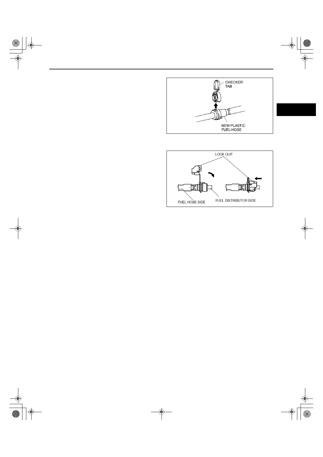
•
A checker tab is integrated with the quick
release connector for new plastic fuel hoses.
The checker tab will be released from the
quick release connector after it is completely
engaged with the fuel pipe.
11. Inspect the plastic fuel hose and fuel pipe sealing
surface for damage and deformation, and replace
if necessary.
•
If the quick release connector O-ring is
damaged or has slipped, replace the plastic
fuel hose.
12. Reconnect the fuel main hose to the fuel
distributor until a click is heard.
13. Pull the quick release connector by hand and verify that it is installed securely.
14. Attach the lock clip to the quick release connector
in the direction of the fuel distributor and lock it,
as shown in the figure.
End Of Sie
FUEL TANK REMOVAL/INSTALLATION
A3U011442110W01
Warning
••••
Repairing a fuel tank that has not been properly steam cleaned can be dangerous. Explosion or
fire may cause death or serious injury. Always properly steam clean a fuel tank before repairing it.
••••
Fuel line spills and leakage are dangerous. Fuel can ignite and cause serious injuries or death and
damage. Fuel can also irritate skin and eyes. To prevent this, do not damage the sealing surface of
the fuel pump unit when removing or installing.
Caution
••••
Disconnecting/connecting the quick release connector without cleaning it may possibly cause
damage to the fuel pipe and quick release connector. Always clean the quick release connector
joint area before disconnecting/connecting, and make sure that it is free of foreign material.
1. Level the vehicle.
2. Complete the “BEFORE REPAIR PROCEDURE”. (See 01–14–4 BEFORE REPAIR PROCEDURE.)
3. Disconnect the negative battery cable.
4. Remove the rear seat cushion. (See 09–13–5 REAR SEAT REMOVAL/INSTALLATION.)
5. Remove the service hole cover.
6. Remove the fuel pump unit.
7. Siphon the fuel from the fuel tank.
8. Remove the presilencer. (See 01–15–1 EXHAUST SYSTEM REMOVAL/INSTALLATION.)
9. Remove in the order indicated in the table.
10. Install in the reverse order of removal.
YMU114WA8
Y3E3912W202
1712-1U-01G(01-14).fm 9 ページ 2001年6月29日 金曜日 午前9時43分