Mazda Protege 5. Manual - part 112
SYMPTOM TROUBLESHOOTING [ENGINE CONTROL SYSTEM (FS)]
01–03B–41
01–03B
NO.19 EXHAUST SMOKE [FS]
A3U010318881W24
Diagnostic procedure
19
Exhaust smoke
DESCRIPTION
•
Blue, black, or white smoke from exhaust system
POSSIBLE CAUSE
Blue smoke (Burning oil):
•
PCV valve malfunction
•
Engine internal oil leakage
White smoke (Water in combustion):
•
Cooling system malfunction (coolant loss)
•
Engine internal coolant leakage
Black smoke (Rich fuel mixture):
•
Air cleaner restriction
•
Intake-air system is collapsed or restricted.
•
Fuel return line is restricted.
•
Excessive fuel pressure
•
Improper engine compression
•
Injector fuel leakage
•
Ignition system malfunction
Warning
The following troubleshooting flow chart contains fuel system diagnosis and repair
procedures. Read following warnings before performing fuel system services:
••••
Fuel vapor is hazardous. It can easily ignite, causing serious injury and damage. Always
keep sparks and flames away from fuel.
••••
Fuel line spills and leakage are dangerous. Fuel can ignite and cause serious injuries or
death and damage. Fuel can also irritate skin and eyes. To prevent this, always complete
“BEFORE REPAIR PROCEDURE” and “AFTER REPAIR PROCEDURE” described in this
manual.
(See 01–14–4 BEFORE REPAIR PROCEDURE.)
(See 01–14–5 AFTER REPAIR PROCEDURE.)
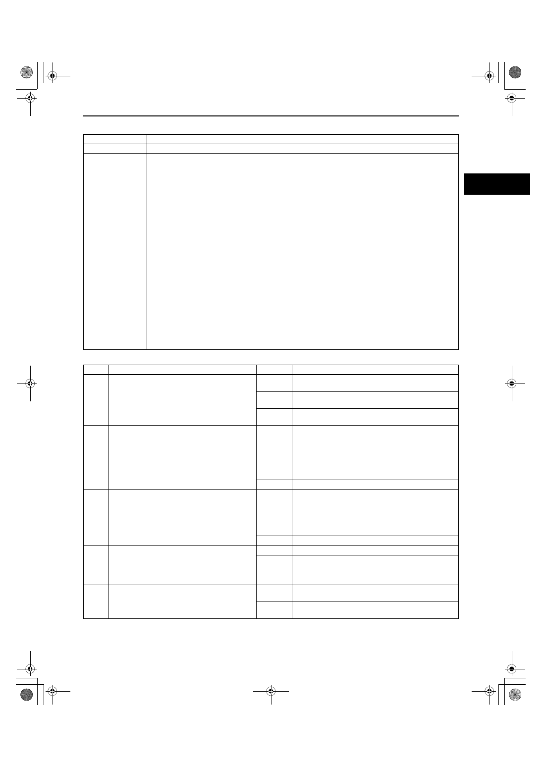
STEP
INSPECTION
RESULTS
ACTION
1
•
What color is smoke coming from exhaust
system?
Blue
Burning oil is indicated.
Go to next step.
White
Water in combustion is indicated.
Go to Step 3.
Black
Rich fuel mixture is indicated.
Go to Step 4.
2
•
Remove and shake PCV valve.
•
Does PCV valve rattle?
Yes
Inspect for following:
•
Damaged valve guide, stems or valve seals
•
Blocked oil drain passage in cylinder head
•
Piston rings for not seated, seized or worn
•
Damaged cylinder bore
If other drivability symptoms are present, return to
diagnostic index to service any additional symptoms.
No
Replace PCV valve.
3
•
Does cooling system hold pressure?
Yes
Inspect for following:
•
Cylinder head gasket leakage
•
Intake manifold gasket leakage
•
Engine block cracks or porosity
If other driveability symptoms are present, return to
diagnostic index to service any additional symptoms.
No
Inspect for cause.
4
•
Inspect for following:
— Air cleaner restriction
— Collapsed or restricted intake-air system
— Restricted fuel return line
•
Are all items okay?
Yes
Go to next step.
No
Service as necessary.
Repeat Step 4.
5
•
Connect WDS or equivalent to DLC-2.
•
Turn ignition key to ON.
•
Retrieve any DTC.
•
Is “DTC” displayed?
Yes
No DTC displayed:
•
Go to next step.
No
DTC displayed:
•
Go to appropriate DTC test.
1712-1U-01G(01-03B).fm 41 ページ 2001年6月29日 金曜日 午前9時33分