Mazda Protege 5. Manual - part 107
SYMPTOM TROUBLESHOOTING [ENGINE CONTROL SYSTEM (FS)]
01–03B–21
01–03B
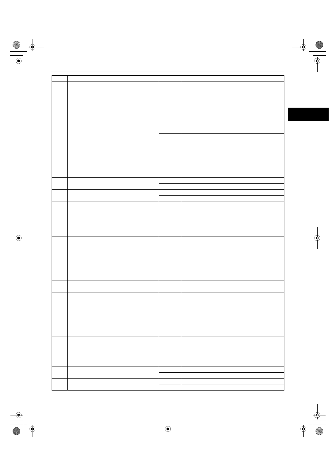
2
•
Connect WDS or equivalent to DLC-2.
•
Turn ignition key to ON.
•
Retrieve any DTC.
•
Is “DTC” displayed?
Yes
DTC displayed:
•
Go to appropriate DTC test.
Communication error message displayed:
•
Inspect for following:
— Open circuit between main relay and PCM
terminal 71 or 97
— Open main relay GND circuit
— Main relay is stuck open.
— Open or poor GND circuit (PCM terminal 24, 51,
76, 77, or 103)
— Poor connection of vehicle body GND
No
No DTC displayed:
•
Go to next step.
3
•
Turn ignition key to LOCK.
•
Disconnect TP sensor connector.
•
Measure voltage at TP sensor connector
VREF terminal with ignition key on.
Voltage
4.5—5.5 V
•
Is voltage okay?
Yes
Go to next step.
No
Go to symptom troubleshooting “NO.30 REFERENCE
VOLTAGE [FS].”
4
•
Does engine start with throttle closed?
Yes
Go to Step 20.
No
Go to next step.
5
•
Will engine start and run smoothly at part
throttle?
Yes
Inspect IAC valve and wiring harness.
No
Go to next step.
6
•
Connect WDS or equivalent to DLC-2.
•
Access RPM PID.
•
Is RPM PID indicating engine speed when
cranking engine?
Yes
Go to next step.
No
Inspect for following:
•
Open or short circuit in CKP sensor
•
Open or short circuit between CKP sensor and
PCM terminal 21 or 22
•
Open or short circuit in CKP sensor harnesses
If CKP sensor and harness are okay, go to next step.
7
•
Visually inspect CKP sensor and teeth of
crankshaft pulley.
•
Are CKP sensor and teeth of crankshaft
pulley okay?
Yes
Go to next step.
No
Replace malfunctioning parts.
8
•
Measure gap between CKP sensor and teeth
of crankshaft pulley.
Gap
0.5—1.5 mm {0.020—0.059 in}
•
Is gap within specification?
Yes
Go to next step.
No
Adjust CKP sensor.
9
•
Inspect for cracks on high-tension leads.
•
Are there any cracks, on high-tension leads?
Yes
Repair suspected high-tension leads.
No
Go to next step.
10
•
Is strong blue spark visible at each
disconnected high-tension lead during
engine cranking ?
Yes
Go to next step.
No
Inspect for following:
•
Open or short circuit in ignition coil
•
Open circuit in high-tension leads
•
Open circuit between ignition coil connector GND
terminal and GND
•
Open circuit between ignition key and ignition coil
•
Open circuit between ignition coil and PCM
terminal 26 or 52
11
•
Inspect condition of spark plugs.
•
Is spark plug wet, covered with carbon or
grayish white?
Yes
Spark plug is wet or covered with carbon:
•
Inspect for fuel leakage from injector.
Spark plug is grayish white:
•
Inspect for clogged fuel injector.
No
Install spark plugs on original cylinders.
Go to next step.
12
•
Remove and shake PCV valve.
•
Does PCV valve rattle?
Yes
Go to next step.
No
Replace PCV valve.
13
•
Is there any restriction in exhaust system?
Yes
Inspect exhaust system.
No
Go to next step.
STEP
INSPECTION
RESULTS
ACTION
1712-1U-01G(01-03B).fm 21 ページ 2001年6月29日 金曜日 午前9時33分