Mazda Protege 5. Manual - part 48
ON-BOARD DIAGNOSTIC [ENGINE CONTROL SYSTEM (FS)]
01–02B–12
Mode 4 (EVAP system repair verification drive mode)
Note
•
If Mode 4 can not be performed (you can not drive the vehicle under Mode 4 condition), perform
evaporative system test procedure as an alternative. (See 01–03B–54 ENGINE CONTROL SYSTEM
OPERATION INSPECTION [FS].)
•
Mode 4 can be performed regardless of RFC FLAG condition.
1. Verify that the following conditions are met. All conditions must be within specifications before engine started to
initiate the evaporative system test.
•
Barometric pressure: 69.7 kPa {523 mmHg, 20.5 inHg} or higher
•
Intake air temperature: –10—60
°°°°
C {14—131
°°°°
F}
•
Fuel tank level: 1.3—3.75 V
•
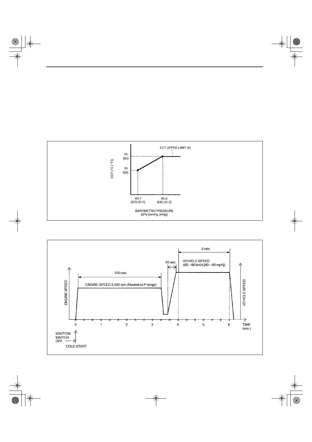
Engine coolant temperature: –10
°°°°
C—X
°°°°
C {14
°°°°
F—X
°°°°
F} (X, the Engine coolant temperature upper limit, is
determined according to the barometric pressure as shown the graph below.)
2. Verify all accessory loads (A/C, headlights, blower fan, rear window defroster) are off.
3. Start the engine and race it at 3,500 rpm to warm up completely.
4. Drive the vehicle as shown in the graph.
5. Stop vehicle and access to ON BOARD SYSTEM READINESS menu of GENERIC OBD II FUNCTION to
inspect the Drive Mode completion status. If completed, RFC changes from NO to YES.
6. If not completed, turn the ignition key off then go back to Step 1.
A3U0102W001
X3U101WBN
1712-1U-01G(01-02B).fm 12 ページ 2001年6月29日 金曜日 午後3時24分