Mazda MX-5 Miata (1997+). Manual - part 15


  Index      Mazda     Mazda MX-5 Miata - service repair manual 1997 year


Search            


Content   ..  13  14  15  16   ..


Mazda MX-5 Miata (1997+). Manual - part 15


Courtesy of MAZDA MOTORS CORP. 

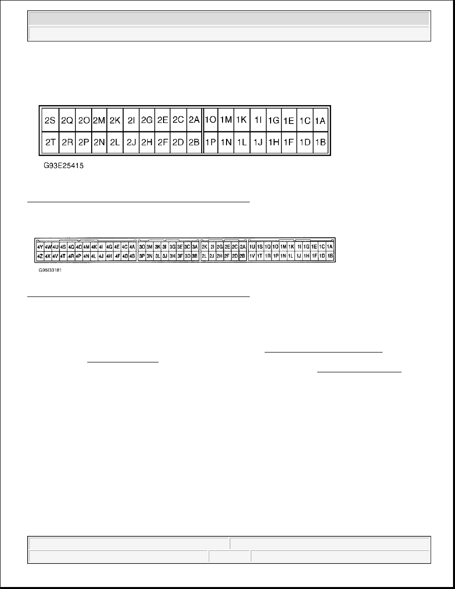
Fig. 4: Identifying TCM Component Connector Terminals 
Courtesy of MAZDA MOTORS CORP. 

Fig. 5: Identifying ECM Component Connector Terminals 
Courtesy of MAZDA MOTORS CORP. 

DIAGNOSTIC TESTS 

DTC P0705: TRANSMISSION RANGE SWITCH CIRCUIT MALFUNCTION & DTC P0706: 
TRANSMISSION RANGE SWITCH CIRCUIT RANGE/PERFORMANCE 

Condition 

No signal is received from range switch or more than 2 signals are received at one time. Possible causes for 
either condition are: 

Transmission range switch malfunction.  

Damaged wiring or connectors between transmission range switch and TCM.  

TCM malfunction.  

Diagnosis & Repair Procedure 

NOTE:

For connector terminal identification, see COMPONENT CONNECTOR 
IDENTIFICATION table under SELF-DIAGNOSTIC SYSTEM. For circuit or wire 
color identification, see appropriate wiring diagram in WIRING DIAGRAMS .


1997 Mazda MX-5 Miata 

1997 AUTOMATIC TRANSMISSIONS NC4A-EL Electronic Controls


1. Ensure all connections are clean and tight. Repair as needed. Turn ignition on. Using voltmeter, 

backprobe TCM connector (as applicable). Measure voltage between ground and specified terminal. See 
DTC P0705 VOLTAGE TEST table. If all voltages are within specification, go to step 5 . If any voltage 
is not within specification, go to next step. 

DTC P0705 VOLTAGE TEST 

2. Check continuity of circuits between transmission range switch and TCM. See appropriate wiring 

diagram in WIRING DIAGRAMS . Repair as needed. If all circuits are okay, go to next step.  

3. Disconnect negative battery cable. Disconnect transmission range switch harness connector. Inspect 

continuity of transmission range switch internal circuits. See TRANSMISSION RANGE SWITCH 
under COMPONENT TESTING. Replace as needed. If switch is okay, go to next step.  

4. Reconnect negative battery cable. Turn ignition on. Measure voltage at terminal "I" (Black/Blue wire) on 

transmission range switch harness connector. If battery voltage does not exist, repair Black/Blue wire 
between switch and ignition switch. If battery voltage exists, go to next step.  

5. Road test vehicle. Retrieve DTC. If code P0705 is still present, replace TCM. If code is no longer present, 

system is okay.  

DTC P0710: TRANSMISSION FLUID TEMPERATURE (TFT) SENSOR CIRCUIT MALFUNCTION 
& DTC P0711: TRANSMISSION FLUID TEMPERATURE (TFT) SENSOR CIRCUIT 
RANGE/PERFORMANCE 

Condition 

Voltage input to TCM is less than .1 volt or greater than 5.0 volts. Possible causes for condition are: 

Transmission fluid temperature sensor malfunction.  

Damaged wiring or connectors between transmission fluid temperature sensor and TCM.  

TCM malfunction.  

Diagnosis & Repair Procedure 

1. Ensure all connections are clean and tight. Repair as needed. Turn ignition on. Access TCM connectors. 

Using voltmeter, backprobe harness connectors. DO NOT disconnect connectors. Go to next step. 

TCM Terminal 
No.

Measured 

Voltage

Range Switch Position

2B

0

"P" Or "N"

2B

10-14

"R", "D", "S" Or "L"

2D

10-14

"D"

2D

0

All Except "D"

2F

10-14

"S"

2F

0

All Except "S"

2H

10-14

"L"

2H

0

All Except "L"


1997 Mazda MX-5 Miata 

1997 AUTOMATIC TRANSMISSIONS NC4A-EL Electronic Controls


2. Measure voltage between terminal No. 1G (Green wire) and No. 2P (Black/Light Blue wire) on TCM 

connector. Voltage should be about 3.3 volts at 77°F (25°C). If voltage is within specifications, go to step 
6 . If voltage is not within specifications, go to next step.  

3. Turn ignition off. Disconnect TCM harness connector. Measure resistance between terminals No. 1G and 

No. 2P. See TFT SENSOR SPECIFICATIONS table. If resistance is within specification, go to step 6 . 
If resistance is not within specification, go to next step.  

4. Inspect TFT sensor. Disconnect TFT sensor harness connector. Measure resistance between connector 

terminals. See TFT SENSOR SPECIFICATIONS table. If resistance is within specification, go to step 
6 . If resistance is not within specification, replace TFT sensor.  

5. Check continuity of circuits between TFT sensor and TCM. See appropriate wiring diagram in WIRING 

DIAGRAMS . Repair as needed. If circuit is okay, go to next step.  

6. Reconnect all harness connectors. Road test vehicle. Retrieve DTC. If code P0710 or P0711 is still 

present, replace TCM. If code is no longer present, system is okay.  

TFT SENSOR SPECIFICATIONS 

DTC P0715: INPUT/TURBINE SPEED SENSOR 

Condition 

Input/Turbine speed sensor signal is not input to TCM when vehicle is moving. Possible causes for condition 
are: 

Input/Turbine speed sensor malfunction.  

Damaged wiring or connectors between turbine speed sensor and TCM.  

TCM malfunction.  

Diagnosis & Repair Procedure 

1. Turn ignition on. Using voltmeter, backprobe TCM harness connector. DO NOT disconnect connector. 

Measure AC voltage between terminals No. 2J (positive) and No. 2L (negative). Voltage should be 0-.1 
volts when idling and zero with engine stopped. If voltage is within specification, go to step 5 . If voltage 
is not within specification, go to next step.  

2. Turn ignition off. Disconnect TCM harness connector. Check for continuity between terminals No. 2J 

(Yellow/Green wire) and No. 2L (Yellow/Blue wire). If continuity is present, go to step 5 . If continuity 
is not present, go to next step.  

3. Inspect sensor. See INPUT/TURBINE SPEED SENSOR under COMPONENT TESTING. Repair as 

needed. If sensor is okay, go to next step.  

4. Check continuity of circuits between input/turbine speed sensor and TCM. See appropriate wiring 

diagram in WIRING DIAGRAMS . Repair as needed. If circuits are okay, go to next step. 

Fluid Temperature

k/ohms

68°F (20°C)

2.5

140°F (60°C)

.6

176°F (80°C)

.35


1997 Mazda MX-5 Miata 

1997 AUTOMATIC TRANSMISSIONS NC4A-EL Electronic Controls


5. Reconnect all harness connectors. Road test vehicle. Retrieve DTC. If code P0715 is still present, replace 

PCM. If code is no longer present, system is okay.  

DTC P0725: ENGINE SPEED INPUT CIRCUIT MALFUNCTION 

Condition 

Engine speed input signal is not input to TCM. Possible causes are: 

Crankshaft position sensor malfunction.  

Damaged wiring or connectors between ECM and TCM.  

ECM malfunction.  

TCM malfunction.  

Diagnosis & Repair Procedure 

1. Ensure all connections are clean and tight. Repair as needed. Turn ignition on. Using voltmeter, 

backprobe TCM harness connector. DO NOT disconnect connector.  

2. Measure voltage between ground and terminal No. 1N (White wire) on TCM harness connector. Voltage 

should be zero or 4.5-5.5 volts with engine stopped or 2-3 volts with engine idling. If voltage is within 
specifications, go to step 7 . If voltage is not within specifications, go to next step.  

3. Ignition off. Measure continuity between terminal No. 1N (White wire) on TCM harness connector and 

terminal No. 4F (White wire) on ECM harness connector. If continuity is not present, repair wiring then 
go to step 7 .  

4. Using voltmeter, backprobe ECM harness connector. Measure voltage between ground and terminal No. 

4H (Yellow/White wire). Voltage should be less than one volt with engine stopped or greater than one 
volt with engine idling. If voltage is within specifications, go to step 7 . If voltage is not within 
specifications, go to next step.  

5. Inspect crankshaft position sensor. See appropriate SYSTEM & COMPONENT TESTS article in 

ENGINE PERFORMANCE. Replace as needed. If sensor is okay, go to next step.  

6. Turn ignition off. Using ohmmeter, backprobe TCM harness connector. DO NOT disconnect connector. 

Measure resistance between terminals 1N (White wire) and 2P (Black/Light Green wire). If resistance is 
7.2-8.0 ohms, go to next step. If resistance is not 7.2-8.0 ohms, replace TCM.  

7. Reconnect all harness connectors. Road test vehicle. Retrieve DTC. If code P0725 is still present, replace 

TCM. If code is no longer present, problem is intermittent.  

DTC P0731: INCORRECT 1ST GEAR RATIO 

NOTE:

If DTC P0335 is also present, repair it first and then proceed with this test. Go to 
appropriate SELF-DIAGNOSTICS article in ENGINE PERFORMANCE and 
perform test.

NOTE:

If any following DTC is also present, repair it first and then proceed with this 
test: DTC P0750 , P0755 , P0760 .


1997 Mazda MX-5 Miata 

1997 AUTOMATIC TRANSMISSIONS NC4A-EL Electronic Controls


Content   ..  13  14  15  16   ..