Mazda 5. Manual - part 28


  Index      Mazda     Mazda 5 - service repair manual


Search            


Content   ..  26  27  28  29   ..


Mazda 5. Manual - part 28


05–17–32

AUTOMATIC TRANSAXLE 

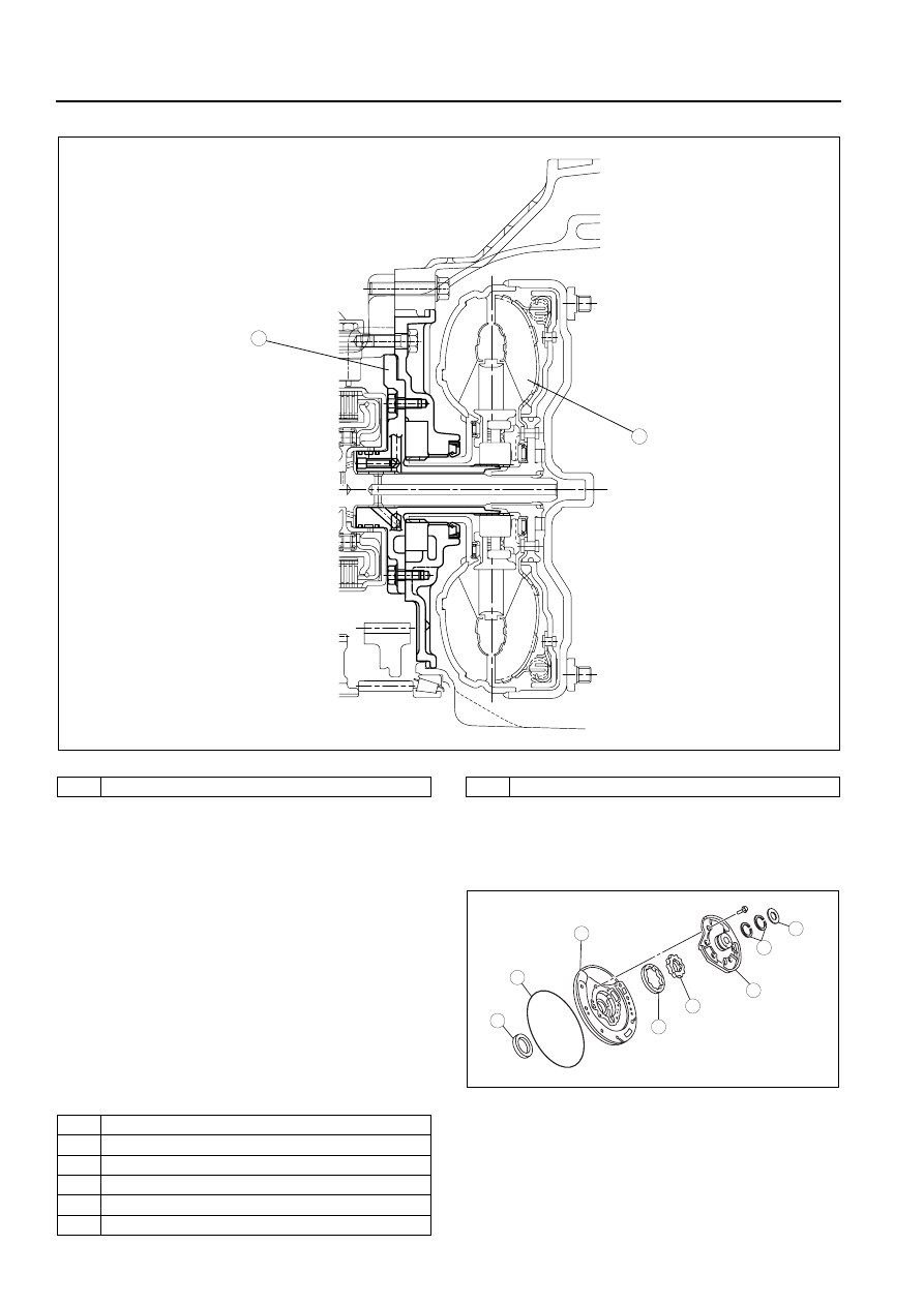
• The direct drive type oil pump is adopted and placed behind the torque converter.

.

End Of Sie

OIL PUMP STRUCTURE

B3E051719220A03

• The outer rotor and the inner rotor are installed in the oil pump housing.

• The inner rotor in the oil pump housing is driven 

by the torque converter.

.

1

2

B3E0517T015

1

Oil pump

2

Torque converter

8

7

5

4

3

6

1

2

B3E0517T016

1

Thrust washer

2

Seal ring

3

Oil pump cover

4

Inner rotor

5

Outer rotor

6

Oil pump housing

AUTOMATIC TRANSAXLE 

05–17–33

05

End Of Sie

OIL PUMP OPERATION

B3E051719220A04

• When the inner rotor in the oil pump rotates, the 

ATF is drawn to the oil pump and then discharged 
from the oil pump. The discharge amount is 
proportional to the rotating speed of the torque 
converter. The ATF discharge amount is 
controlled by the pressure regulator valve and the 
pressure control solenoid.

.

End Of Sie

FORWARD CLUTCH, 3-4 CLUTCH HYDRAULIC CIRCUIT OUTLINE

B3E051701030A26

• By designing exclusive passages for the forward clutch and the 3-4 clutch in the transaxle case, via the oil 

pump and end cover the hydraulic pressure passages are shortened and control during clutch engagement is 

7

O-ring

8

Oil seal

4

3

1

2

B3E0517T017

1

Out

2

In

3

Oil strainer

4

Pressure regulator valve

05–17–34

AUTOMATIC TRANSAXLE 

improved.

.

End Of Sie

CONTROL VALVE BODY OUTLINE

B3E051721100A01

• The control valve body is composed of three bodies: the upper control valve body, premain control valve body, 

and the solenoid control valve body.

• Because the clutch engagement pressure is controlled electronically, the hydraulic circuits are simplified, the 

valve types are reduced, and the control valve body is miniaturized.

5

4

3

6

1

2

5

4

1

2

B3E0517T019

1

Oil pump

2

Forward clutch hydraulic passage

3

Forward clutch

4

End  cover

5

3-4 clutch hydraulic passage

6

3-4  clutch

AUTOMATIC TRANSAXLE 

05–17–35

05

• The nonwoven fabric oil strainer is installed in the control valve body to prevent contamination.

.

End Of Sie

9

8

7

5

4

3

10

6

1

2

B3E0517T018

1

Upper control valve body

2

Main control valve body

3

Oil strainer

4

Solenoid valve body

5

Shift solenoid A

6

Shift solenoid B

7

Shift solenoid C

8

Shift solenoid D

9

Shift solenoid E

10

Pressure control solenoid


Content   ..  26  27  28  29   ..