Lifan 620. Manual - part 84
(3) Remove the left rear seat back assembly, as shown in Fig. 7-11.
①
③
①
②
③
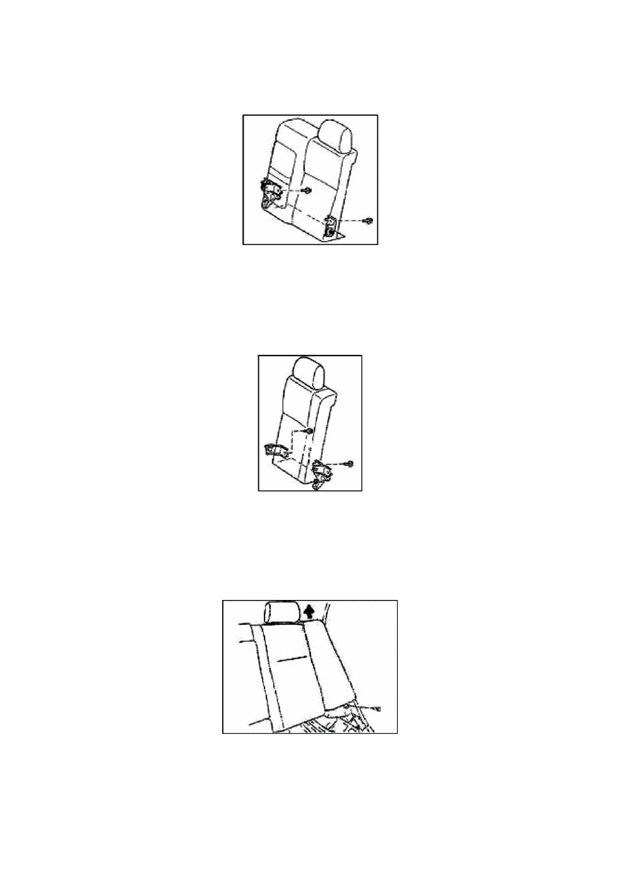
Fig. 7-13
Remove the bottom fixing bolts on the left side b
①
ack of the rear seat.
Pull out the
②
left side back and the Fig. 7-13 may be referred.
337