Lifan 620. Manual - part 9


  Index      Lifan     Lifan 620 - service repair manual 2008 year


Search            


Content   ..  7  8  9  10   ..


Lifan 620. Manual - part 9


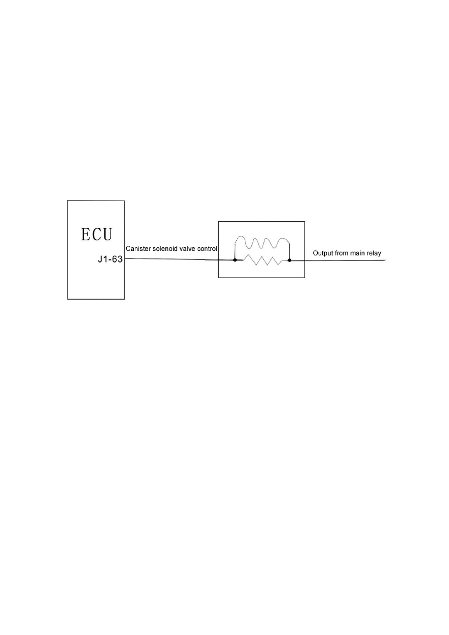
difference between the inlet and outlet hole. When no electric pulse is produced, the canister 
control valve will be closed. According to the signals from each sensor, the ECU can control the 
time for power connection of the canister solenoid valve, and then control the volume of the 
cleaning air flow. 

(3) Trouble diagnosis:

 The ECU will carry out trouble diagnosis for the driving stage of the 

canister control valve. When the driving stage of the canister control valve is short or overloaded to 
the battery voltage, as well as short and open to the ground, the fuel ration closed loop control 
self-learning and the idle speed air ration self-learning will be closed, while the self-leaning data at 
that moment will be effective. When the canister solenoid valve is under trouble, the engine is 
likely to experience unstable idle speed or over-high idle speed. 


37

Section III      Steps for Trouble Diagnosis with DTC 


I   LF Self-developed Engine

 (LF481Q3) 

1. A/C evaporator outlet temperature sensor

   (see Table 1-3) 


Table 1-3 

Diagnostic Trouble Code (DTC) 

Trouble Location or Type 

P1535 

A/C evaporator temperature circuit high input---short or open to power supply


multimeter. Is the resistance between 1.6k and 2.4k? 

No Replace 

sensor 

Yes Replace 

sensor 

Slowly turn the throttle position sensor from one side to 

the other side. Check for open or short circuit or a jump 

resistance between pin (1) (-) and pin (3) (+) with a 

multimeter.  


No 

Replace ECU 

Connect an adapter between the ECU and the harness. 

Check for open or short circuit between pin J1-20, J1-05, 

J1-24 of the ECU and the pin (1), (2), (3) of the sensor 

with a multimeter. 

Yes 

Repair or replace harness 

38

3. Shock sensor

  (see Table 1-5) 

 
Table 1-5 

Diagnostic Trouble Code (DTC) 

Trouble Location or Type 

P0325 

Shock sensor 1 circuit trouble 

S/N Operation Test 

Results 

Actions 

Turn off the ignition switch, and stop the engine. 


Next step 

Yes Next 

step 

Disconnect the shock sensor from the harness. 

Measure the resistance between pin (1) and pin (2) 

No Renew 

sensor 


of the sensor with a multimeter. 

Turn on the ignition switch, and do not start the 

engine. 

 Next 

step 

Yes Replace 

ECU 

In neutral position, start the engine, and keep idle 

speed. Step on the accelerator. Through the adapter, 

measure the voltage between pin (4) and pin (1) with 

a multimeter, namely between pin J1-42 and pin J1-21 

of the ECU. Does the voltage gradually increase to 

4V? 

No 

Replace ECU 

Replace sensor 

39

5. Oxygen sensor   

(see Table 1-7) 


Table 1-7 

Diagnostic Trouble Code (DTC) 

Trouble Location or Type 

P0031 

Heated oxygen sensor heater control circuit low (front) 

P0032 

Heated oxygen sensor heater control circuit high (front) 

P0037 

Heated oxygen sensor heater control circuit low (rear) 

P0038 

Heated oxygen sensor heater control circuit high (rear) 

P0130 

Oxygen sensor circuit trouble (front) 

reaches normal temperatue. 

Yes Next 

step 

Disconnect the oxygen sensor from the harness. 

Measure the voltage between pin (4) (+) and pin (3) 

(-) with a multimeter. Is the voltage between 0.1V and 

0.9V? 

No Replace 

sensor 

Yes 

Repair or replace harness

Connect an adapter between the ECU and the 

harness. Check for open or short circuit between pin 

J1-06, pin J1-62 (front)/ J1-38 (rear) of the ECU and 

pin (3), pin (4) of the sensor with a multimeter. 

No Replace 

ECU 

40


Content   ..  7  8  9  10   ..