LEXUS UX 200 (2019 year). Instruction - part 13
204
4-5. Using the driving support systems
currently traveled lane, such a sign exists
directly after a freeway branches, or in an
adjacent lane just before merging.
●
Stickers are attached to the rear of the
preceding vehicle.
●
A sign resembling a system compatible
sign is recognized.
●
Side road speed signs may be detected
and displayed (if positioned in sight of the
front camera) while the vehicle is travel-
ing on the main road.
●
Roundabout exit road speed signs may
be detected and displayed (if positioned
in sight of the front camera) while travel-
ing on a roundabout.
●
The front of the vehicle is raised or low-
ered due to the carried load.
●
The surrounding brightness is not suffi-
cient or changes suddenly.
●
When a sign intended for trucks, etc. is
recognized.
●
Vehicles with navigation system: The
speed information displayed on the
meter and that displayed on the naviga-
tion system may be different due to the
navigation system using map data.
■
Speed limit sign display
If the engine switch was last turned off while
a speed limit sign was displayed on the
multi-information display, the same sign dis-
plays again when the engine switch is
turned to ON.
■
Customization
Some functions can be customized. (Cus-
tomizable features:
■
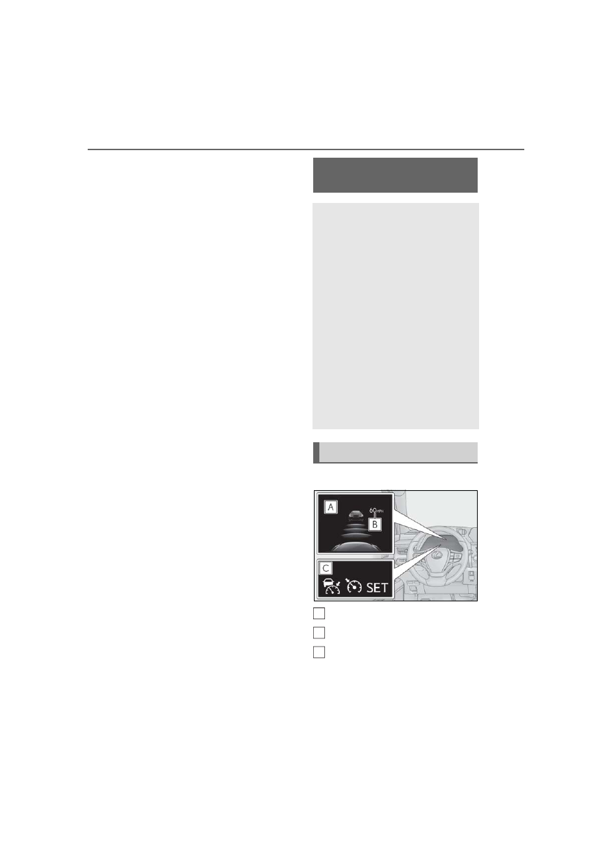
Meter display
Multi-information display
Set speed
Indicators
Dynamic radar cruise con-
trol with full-speed range
In vehicle-to-vehicle distance con-
trol mode, the vehicle automati-
cally accelerates, decelerates and
stops to match the speed changes
of the preceding vehicle even if the
accelerator pedal is not depressed.
In constant speed control mode,
the vehicle runs at a fixed speed.
Use the dynamic radar cruise con-
trol with full-speed range on free-
ways and highways.
Vehicle-to-vehicle distance con-
trol mode (
Constant speed control mode
(
P.211)
System Components
A
B
C