Lexus RX300 (MCU15). Manual - part 367
 

  Index      Lexus     Lexus RX300 series MCU15 - service repair manual


Search            


Content   ..  365  366  367  368   ..


Lexus RX300 (MCU15). Manual - part 367


I07388

C11

MPX+

MPX–

I19185

MPX+ MPX–

Center Cluster Integration Panel

MPX+

”I17”

”I16”

DI–698

–

DIAGNOSTICS

MULTIPLEX COMMUNICATION SYSTEM

LEXUS RX300   (RM785E)

9

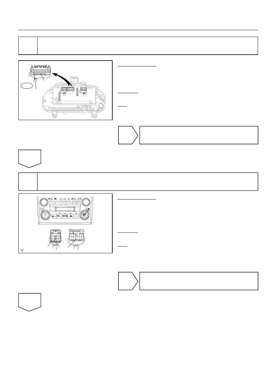
Check the communication circuit inside A/C and combination meter integrated
ECU.

PREPARATION:
(a)

Connect the connector ”T5” of theft deterrent ECU.

(b)

Disconnect the connector ”C11” of A/C and combination
meter integrated ECU.

CHECK:
Check the DTC.
OK:
Code B1214/14 or B1215/15 is not output.

OK

Replace the A/C and combination meter inte-
grated ECU.

NG

10

Check the communication circuit inside center cluster integration panel.

PREPARATION:
(a)

Connect the connector ”C11” of A/C combination meter
integrated ECU.

(b)

Disconnect the connector ”I16 (Except Europe)” or ”I17
(Europe)” of center cluster integration panel.

CHECK:
Check the DTC.
OK:
Code B1214/14 or B1215/15 is not output.

OK

Replace the center cluster integration panel.

NG

I19213

”I16”

”I17”

MPX+

”B5”

Body ECU

Center Cluster

I19214

MPX–

”I16”

”I17”

–

DIAGNOSTICS

MULTIPLEX COMMUNICATION SYSTEM

DI–699

LEXUS RX300   (RM785E)

11

Check for short circuit between center cluster integration panel and body ECU.

PREPARATION:
Disconnect the connector ”B5” of body ECU and ”I16 (Except
Europe)” or ”I17 (Europe)” of center cluster integration panel.
CHECK:
Check continuity between terminal MPX+ of center cluster in-
tegration panel and body ground.
OK:

No continuity.

CHECK:
Measure voltage between terminal MPX+ of center cluster in-
tegration panel and body ground.
OK:

No voltage.

OK

Repair or replace the wireharness between cen-
ter cluster integration panel and body ECU.

NG

12

Check for short circuit between center cluster integration panel and A/C and
combination meter integrated ECU.

PREPARATION:
(a)

Connect the connector ”B8” of body ECU.

(b)

Disconnect the connector ”C11” of A/C combination me-
ter integrated ECU.

CHECK:
Check continuity between terminal MPX– of center cluster in-
tegration panel.
OK:

No continuity.

CHECK:
Measure voltage between terminal MPX– of center cluster in-
tegration panel.
OK:

No voltage.

NG

Repair or replace the wireharness between cen-
ter cluster integration panel and A/C and com-
bination ECU.

OK

I19215

MPX–

”t5”

Theft Deterrent

I19216

Driver Door ECU

MPX2

Theft Deterrent ECU

”T5”

DI–700

–

DIAGNOSTICS

MULTIPLEX COMMUNICATION SYSTEM

LEXUS RX300   (RM785E)

13

Check short circuit between A/C and combination meter integrated ECU and
theft deterrent ECU.

PREPARATION:
(a)

Connect the connector of center cluster integration panel.

(b)

Disconnect the connector ”T5” of theft deterrent ECU.

CHECK:
Check continuity between terminal MPX– of A/C and combina-
tion meter integrated ECU and body ground.
OK:

No continuity.

CHECK:
Measure voltage between terminal MPX– of A/C and combina-
tion meter integrated ECU and body ground.
OK:

No voltage.

NG

Repair or replace the wireharness between A/C
and combination meter integrated ECU and
theft deterrent ECU.

OK

14

Check for short circuit between theft deterrent ECU and driver door ECU.

PREPARATION:
(a)

Connect the connector of A/C and combination meter in-
tegrated ECU.

(b)

Disconnect the connector of driver door ECU.

CHECK:
Check continuity between terminal MPX2 of theft deterrent
ECU and body ground.
OK:

No continuity.

CHECK:
Measure voltage between terminal MPX2 of theft deterrent
ECU and body ground.
OK:

No voltage.

NG

Repair or replace the wireharness between driv-
er door ECU and theft deterrent ECU.

OK

I19217

Driver Door ECU

”R13”

MPX2

Rear Left Door ECU

I19218

Double Lock Control
Relay

”R13”

MPX2

Rear Left Door ECU

–

DIAGNOSTICS

MULTIPLEX COMMUNICATION SYSTEM

DI–701

LEXUS RX300   (RM785E)

15

Check for short circuit between driver door ECU and rear left door ECU.

PREPARATION:
(a)

Connect the connector of theft deterrent ECU.

(b)

Disconnect the connector ”R13” of rear left door ECU.

CHECK:
Check continuity between terminal MPX2 of driver door ECU
and body ground.
OK:

No continuity.

CHECK:
Measure voltage between terminal MPX2 of driver door ECU
and body ground.
OK:

No voltage.

NG

Repair or replace the wireharness between driv-
er door ECU and rear left ECU.

OK

16

Check for short circuit between rear left door ECU and double lock control relay.

PREPARATION:
(a)

Connect the connector of driver door ECU.

(b)

Disconnect the connector of double lock control relay.

CHECK:
Check continuity between terminal MPX2 of rear left door ECU
and body ground.
OK:

No continuity.

CHECK:
Measure voltage between terminal MPX2 of rear left door ECU
and body ground.
OK:

No voltage.

NG

Repair or replace the wireharness between the
rear left door ECU and double lock control relay.

OK


Content   ..  365  366  367  368   ..