Lexus SC300 / Lexus SC400. Manual - part 658


  Index      Lexus     Lexus SC300 / Lexus SC400 - service repair manual


Search            


Content   ..  656  657  658  659   ..


Lexus SC300 / Lexus SC400. Manual - part 658


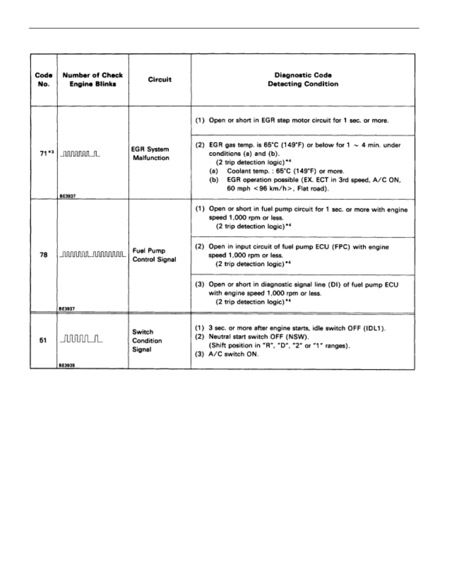
DIAGNOSTIC CODE CHART (Cont’d)

*1: ”ON” displayed in the diagnosis mode column indicates that the ”CHECK” Engine Warning Light is

lighted up when a malfunction is detected. ”OFF” indicates that the ”CHECK” does not light up during
malfunction diagnosis, even if a malfunction is detected. ”N.A.” indicates that the item is not included
in malfunction diagnosis.

*2: ”O” in the memory column indicates that a diagnostic code is recorded in the ECU memory when a mal-

function occurs. ”X” indicates that a diagnostic code is not recorded in the ECU memory even if a mal-
function occurs. Accordingly, output of diagnostic results in normal or test mode is performed with the
IG switch ON.

*3: Only for USA specification vehicles.

TR–20

ENGINE TROUBLESHOOTING

Diagnostic Code Chart

Trouble Area

”CHECK”

Engine Warning

Light*


Memory*


See Page

Trouble Area

Normal

Mode

Test

Mode

Memory

See Page

 Open or short in EGR step motor circuit.

ON

N A

 O en or short in EGR ste  motor circuit.

 ECU

ON

N.A.

 Open in EGR gas temp. sensor circuit.

ON

ON


TR–108

 O en in EGR gas tem . sensor circuit.

 ECU

ON

ON

 Open or short in fuel pump ECU circuit.

 Fuel pump ECU

 Engine & ECT ECU power source circuit.

 Fuel pump

 Engine & ECT ECU

ON

ON


TR–114

 A/C switch circuit

 Throttle position sensor IDL circuit

 Neutral start switch circuit.

 Accelerator pedal and cable

 ECU

N.A.

OFF

X

TR–118

*4:

This indicates items for which ”2 trip detection logic” is used. With this logic, when a logic malfunction is
first detected, the malfunction is temporarily stored in the ECU memory. If the same case is detected again
during the second drive test, this second detection causes the ”CHECK” Engine Warning Light to light up.
The 2 trip repeats the same mode a 2nd time. (However, the IG switch must be turned OFF between the
1st trip and 2nd trip).
In the Test Mode, the ”CHECK” Engine Warning Light lights up the 1st trip a malfunction is detected.

ENGINE TROUBLESHOOTING

Diagnostic Code Chart

TR–21

FAIL–SAFE CHART

If any of the following codes is recorded, the ECU enters fail–
safe mode.

Code No.

Fail–Safe Operation

Fail–Safe Deactivation Conditions

14

Fuel cut

1 IGF1 detected in consecutive 8 ignitions.

15

Fuel cut

1 IGF2 detected in consecutive 8 ignitions.

16

Torque control prohibited.

Returned to normal condition.

22

THW is fixed at 80

°

C (176

°

F).

Returned to normal condition.

24

THA is fixed at 20

°

C (68

°

F).

Returned to normal condition.

31

Ignition timing controlled between 10

°

 ~ 30

°

BTDC,
Injection time controlled between 3 msec. ~ 30 m
sec., in relation to:

Engine rpm

Throttle angle

ISC step value

KS input 15 times/sec. or more.

35

Atmospheric pressure is fixed at 760 mmHg.

Returned to normal condition.

The following 1 or 2 must be repeated at least 2

times consecutively.

41

VTA1 is fixed at 0

°

1

When IDL is ON

41

VTA1 is fixed at 0

°

1

When IDL is ON
0.25 V 


 VTA1 


 0.95 V

2

When IDL is OFF

2

When IDL is OFF
0.25 V 


 VTA1 


 4.9 V

The following 1 or 2 must be repeated at least 2

times consecutively.

47

Value of VTA1 is used

1

When IDL2 is ON

47

Value of VTA1 is used.

1

When IDL2 is ON
0.25 V 


 VTA2 


 0.95 V

2

When IDL2 is OFF

2

When IDL2 is OFF
0.25 V 


 VTA2 


 4.9 V

52

Max. timeing retardation.

IG switch OFF.

53

Max. timeing retardation.

Returned to normal condition.

55

Max. timeing retardation.

IG switch OFF.

Back–Up Function
If there is trouble with the program in the ECU and the ignition signals (IGT) are not output, the ECU controls
fuel injection and ignition timing at predetermined levels as a back–up function to make it possible to continue
to operate the vehicle.
Furthermore, the injection duration is calculated from the satrting signal (STA) and the throttle position signal
(IDL). Also, the ignition timing is fixed at the initial ignition timing, 5

°

 BTDC, without relation to the engine speed.

HINT: If the engine is controlled by the back–up function, the CHECK ENGINE light lights up to warn the driver
of the malfunction but the diagnostic code is not output.

TR–22

ENGINE TROUBLESHOOTING

Fail–Safe Chart

CHECK FOR MOMENTARY
INTERRUPTION

As described in the preceding paragraph, abnormality detection
ability in the test mode is increased compared to that in the normal
mode, so that when momentary interruptions or momentary shorts
occur in the ECU signal circuits (G1, G2, NE, THW, THA, VTA1,
VTA2) shown in the table below, the appropriate diagnostic code
is output.
Accordingly, when the diagnostic codes shown in the table below
(13, 22, 24, 41, 47) are output during the diagnostic code check,
and inspection of the appropriate circuits reveals no abnormality,
perform the check for momentary interruption as described below.
By performing the check for momentary interruption, the place
where momentary interruptions or momentary shorts are occur-
ring due to poor contacts can be isolated.

CLEAR DIAGNOSTIC CODES

See page 

TR–13

.

SET TEST MODE

1. 

With the ignition switch off, using SST, connect the terminals
TE2 and E1 of the TDCL.
SST 09843–18020

2.  Start the engine and check to see the ”CHECK” engine

warning light to go off.

PERFORM A SIMULATION TEST

Using the symptom simulation (See page 

IN–20

), apply vibration

to and pull lightly on the wire harness, connector or terminals in the
circuit indicated by the malfunction code.
In this test, if the ”CHECK” engine warning light lights up, it indi-
cates that the place where the wire harness, connector or termi-
nals being pulled or vibrated has faulty contact. Check that point
for loose connections, dirt on the terminals, poor fit or other prob-
lems and repair as necessary.
HINT: After cancelling out the diagnostic code in memory and set
the test mode, if the ”CHECK” engine warning light does not go off
after the engine is started, check thoroughly for faulty contact,
etc., then try the check again. If the ”CHECK” engine warning light
still does not go off, check and replace ECU.

ENGINE TROUBLESHOOTING

Check for Momentary Interruption

TR–23


Content   ..  656  657  658  659   ..